(Rear piping hole)
(Rear piping hole)
Left
Right
Mark center of indoor
unit on rear panel
Space to
the wall
(150mm)
above
Space to
the wall
above
Wall
Wall
5.91 in.
(150mm)
5.91 in.
Indoor
Outdoor
Wall pipe
Chalk
(field supplied)
Wrenched
Bent
Flooded
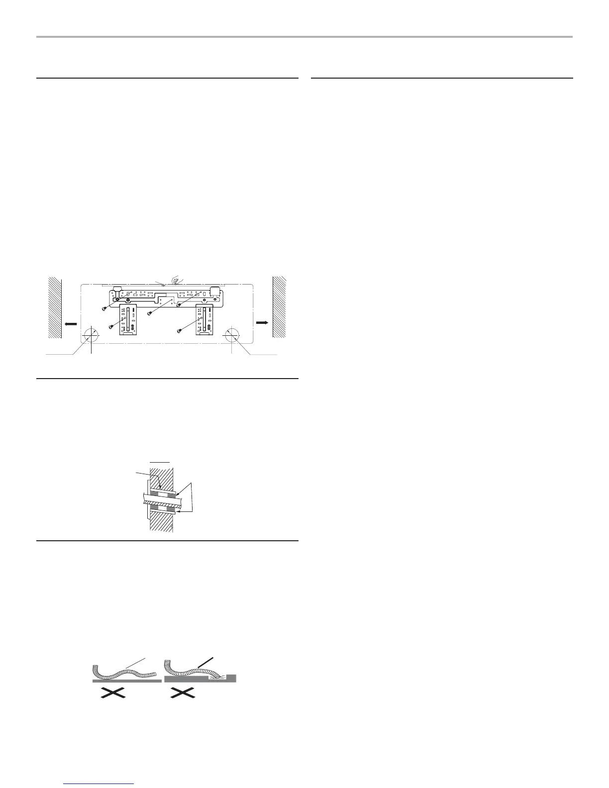
INSTALLING THE INDOOR UNIT
Installing the Rear Panel
1. First fi nd the center of the indoor unit in relation to the
rear panel before mounting to the wall. If rear panel is
not attached to the indoor unit, place the rear panel on
the indoor unit as it will later be attached. Find the center
(right to left) of the indoor unit and mark that position on
rear panel.
2. Place the rear panel in the desired location on the wall.
Always install the rear panel horizontally and level right
to left to facilitate condensate water drainage.
3. Attached rear panel to the wall with heavy-duty screws.
4. Rear panel should be solidly attached to the wall,
enough to withstand the weight of 132 lbs (60 kg).
Weight should be evenly distributed among the screws.
Installing the Piping Hole
1. Drill the piping hole at a slight downward angle to the
outside.
2. Insert the piping-hole sleeve into the prepared hole to
prevent damage to piping and wiring. (fi eld supplied).
Installing the Condensate Water Drain
1. For wall drainage, the condensate pipe should be
installed at a slight downward angle.
2. Do not pull or bend the condensate pipe. No trap
requirement.
3. Wrapping the condensate hose in insulation is
recommended.
Connecting Indoor and Outdoor
Electrical Wiring
1. All wiring should follow the enclosed wiring diagrams.
2. Tilt front panel up.
3. Remove cover plate screws and remove cover plate.
4. Put the power connection cable through the hole in the
back of the indoor unit and pull it out as far as it will go.
5. Put the sheathed power connection cable into the wire
groove; reattach cover plate with screws. Tighten the
connection wire.
6. Replace front panel cover.
7. Signal connection wire should be passed through the
indoor unit connection using wire clip under the body
case. Tighten the connection wire.
NOTE: If electric connection cable is not long enough,
contact qualifi ed service professional for cable of correct
length.
• Incorrect connection of electrical connection cable can
cause malfunction in unit.
• Securely tighten the terminal screw to keep it from coming
loose.
• After tightening the terminal screw, pull slightly on wire to
assure tight connection.
• Make sure ground wire is properly attached to prevent
electric shock.
• The cover plate must be fi rmly closed and connection wire
tightened to prevent dust, debris and condensation from
forming inside the unit, which could cause fi re or electric
shock.
• Circuit breaker must be of correct capacity for safe
operation.
17
 Loading...