51
Technical Information
Service Manual
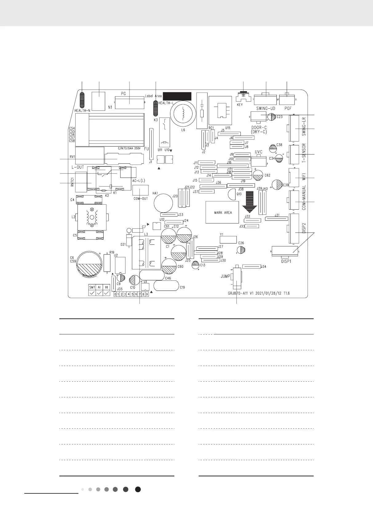
5.2 PCB Printed Diagram
Indoor Unit
8
9
11
13
No. Name No. Name
1 Interface of health function neutral wire 10 Terminal of temperature sensor
2 Neutral wire terminal 11 WIFI terminal
3 Motor terminal 12 Wired controller terminal
4 Interface of health function live wire 13 Interface of display board
5 Auto button 14 Jumper cap
6 Up&down swing terminal 15
Communication terminal for indoor unit
and outdoor unit
7 Interface of Motor feedback 16
Terminal of live wire used for supplying
power for outdoor unit
8 Interface of gate-control 17 Live wire terminal
9 Left&right swing terminal 18 Fuse
07K/09K/12K
GWH18QD-K6DNB2E/I GWH18QD-K6DNC4A/I
 Loading...