68
Installation and Maintenance
Service Manual
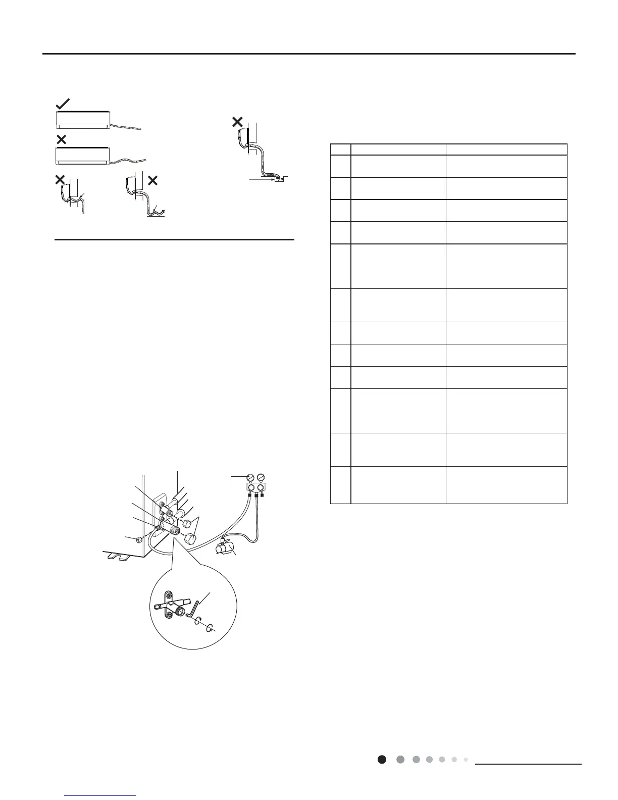
7KHZDWHURXWOHWFDQWEHSODFHGLQZDWHULQRUGHUWRGUDLQ
VPRRWKO\$VVKRZLQ)LJ
Liquid valve
Gas valve
Refrigerant charging
vent
Nut of refrigerant
Charging vent
Vacuum pump
Piezometer
Valve cap
Lo Hi
Inner hexagon
spanner
Open
Close
The drain hose can't be fluctuant
The drain hose
can't be fluctuant
The water
outlet can't be
fluctuant
NO. ,WHPVWREHFKHFNHG 3RVVLEOHPDOIXQFWLRQ
1
+DVWKHXQLWEHHQ
LQVWDOOHG¿UPO\"
7KHXQLWPD\GURSVKDNHRU
emit noise.
2
+DYH\RXGRQHWKH
UHIULJHUDQWOHDNDJHWHVW"
,WPD\FDXVHLQVXI¿FLHQWFRROLQJ
KHDWLQJFDSDFLW\
3
,VKHDWLQVXODWLRQRI
SLSHOLQHVXI¿FLHQW"
,WPD\FDXVHFRQGHQVDWLRQDQG
water dripping.
4 ,VZDWHUGUDLQHGZHOO"
,WPD\FDXVHFRQGHQVDWLRQDQG
water dripping.
5
,VWKHYROWDJHRISRZHU
VXSSO\DFFRUGLQJWRWKH
YROWDJHPDUNHGRQWKH
QDPHSODWH"
,WPD\FDXVHPDOIXQFWLRQRU
GDPDJHWKHSDUWV
6
Is electric wiring and
pipeline installed
FRUUHFWO\"
,WPD\FDXVHPDOIXQFWLRQRU
GDPDJHWKHSDUWV
7
,VWKHXQLWJURXQGHG
VHFXUHO\"
,WPD\FDXVHHOHFWULFOHDNDJH
8
'RHVWKHSRZHUFRUG
IROORZWKHVSHFL¿FDWLRQ"
,WPD\FDXVHPDOIXQFWLRQRU
GDPDJHWKHSDUWV
9
,VWKHUHDQ\REVWUXFWLRQ
LQDLULQOHWDQGDLURXWOHW"
,WPD\FDXVHLQVXI¿FLHQWFRROLQJ
KHDWLQJ
10
7KHGXVWDQG
VXQGULHVFDXVHG
GXULQJLQVWDOODWLRQDUH
UHPRYHG"
,WPD\FDXVHPDOIXQFWLRQRU
GDPDJLQJWKHSDUWV
11
7KHJDVYDOYHDQGOLTXLG
YDOYHRIFRQQHFWLRQSLSH
DUHRSHQFRPSOHWHO\"
,WPD\FDXVHLQVXI¿FLHQWFRROLQJ
KHDWLQJFDSDFLW\
12
,VWKHLQOHWDQGRXWOHW
RISLSLQJKROHEHHQ
FRYHUHG"
,WPD\FDXVHLQVXI¿FLHQWFRROLQJ
KHDWLQJFDSDFLW\RUZDVWHU
eletricity.
The water outlet
can't be placed
in water
1. Use Vacuum Pump
5HPRYHWKHYDOYHFDSVRQWKHOLTXLGYDOYHDQGJDVYDOYH
DQGWKHQXWRIUHIULJHUDQWFKDUJLQJYHQW
&RQQHFWWKHFKDUJLQJKRVHRISLH]RPHWHUWRWKHUHIULJHUDQW
FKDUJLQJYHQWRIJDVYDOYHDQGWKHQFRQQHFWWKHRWKHUFKDUJLQJ
KRVHWRWKHYDFXXPSXPS
2SHQWKHSLH]RPHWHUFRPSOHWHO\DQGRSHUDWHIRUPLQ
WRFKHFNLIWKHSUHVVXUHRISLH]RPHWHUUHPDLQVLQ03D
&ORVHWKHYDFXXPSXPSDQGPDLQWDLQWKLVVWDWXVIRUPLQ
WRFKHFNLIWKHSUHVVXUHRISLH]RPHWHUUHPDLQVLQ03D,I
WKHSUHVVXUHGHFUHDVHVWKHUHPD\EHOHDNDJH
5HPRYHWKHSLH]RPHWHURSHQWKHYDOYHFRUHRIOLTXLGYDOYH
DQGJDVYDOYHFRPSOHWHO\ZLWKLQQHUKH[DJRQVSDQQHU
7LJKWHQWKHVFUHZFDSVRIYDOYHVDQGUHIULJHUDQWFKDUJLQJ
YHQW$VVKRZLQ)LJ
1. Check after Installation
&KHFNDFFRUGLQJWRWKHIROORZLQJUHTXLUHPHQWDIWHU¿QLVKLQJ
installation.
2. Test Operation
(1) Preparation of test operation
Ɣ7KHFOLHQWDSSURYHVWKHDLUFRQGLWLRQHULQVWDOODWLRQ
Ɣ6SHFLI\WKHLPSRUWDQWQRWHVIRUDLUFRQGLWLRQHUWRWKHFOLHQW
0HWKRGRIWHVWRSHUDWLRQ
Ɣ3XWWKURXJKWKHSRZHUSUHVV212))EXWWRQRQWKHUHPRWH
controller to start operation.
Ɣ3UHVV02'(EXWWRQWRVHOHFW$872&22/'5<)$1DQG
+($7WRFKHFNZKHWKHUWKHRSHUDWLRQLVQRUPDORUQRW
Ɣ,IWKHDPELHQWWHPSHUDWXUHLVORZHUWKDQ
ć
WKHDLU
FRQGLWLRQHUFDQ¶WVWDUWFRROLQJ
2. Leakage Detection
:LWKOHDNDJHGHWHFWRU
&KHFNLIWKHUHLVOHDNDJHZLWKOHDNDJHGHWHFWRU
:LWKVRDSZDWHU
,IOHDNDJHGHWHFWRULVQRWDYDLODEOHSOHDVHXVHVRDSZDWHUIRU
OHDNDJHGHWHFWLRQ$SSO\VRDSZDWHUDWWKHVXVSHFWHGSRVLWLRQ
DQGNHHSWKHVRDSZDWHUIRUPRUHWKDQPLQ,IWKHUHDUHDLU
EXEEOHVFRPLQJRXWRIWKLVSRVLWLRQWKHUHVDOHDNDJH
8.7 Vacuum Pumping and Leak
Detection
8.8 Check after Installation and Test
Operation
Fig.26
Fig.27
Fig.28
 Loading...