16
Technical Information
Service Manual
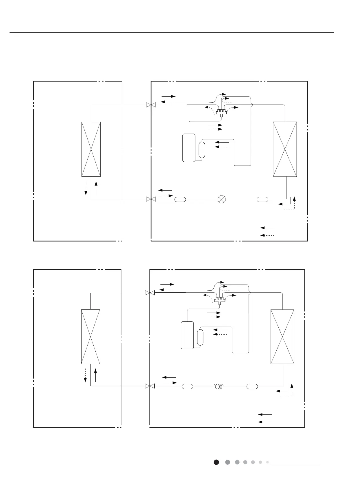
4. Refrigerant System Diagram
Cooling and heating model
Cooling and heating model
&RQQHFWLRQSLSHVSHFL¿FDWLRQ
/LTXLGSLSHPP
*DVSLSHPP*:+$$'.'1$%*:+$$'.'1$%*:+$$'.'1$%
*DVSLSHPP*:+$$'.'1$$
*DVSLSHPP.
Indoor unit
Outdoor unit
COOLING
HEATING
4-Way valve
Discharge
Suction
Heat
exchanger
(evaporator)
Heat
exchanger
(condenser)
Valve
Valve
Liquid pipe
side
Gas pipe
side
Strainer Electric
expand
valve
Strainer
Compressor
Accumlator
Indoor unit
Outdoor unit
COOLING
HEATING
4-Way valve
Discharge
Suction
Heat
exchanger
(evaporator)
Heat
exchanger
(condenser)
Valve
Valve
Liquid pipe
side
Gas pipe
side
Strainer Capillary Strainer
Accumlator
Compressor
GWH18AAD-K6DNA1A
24K
GWH18AAD-K6DNA1B
 Loading...