HVLS Standard Touchscreen Control4
First Fan
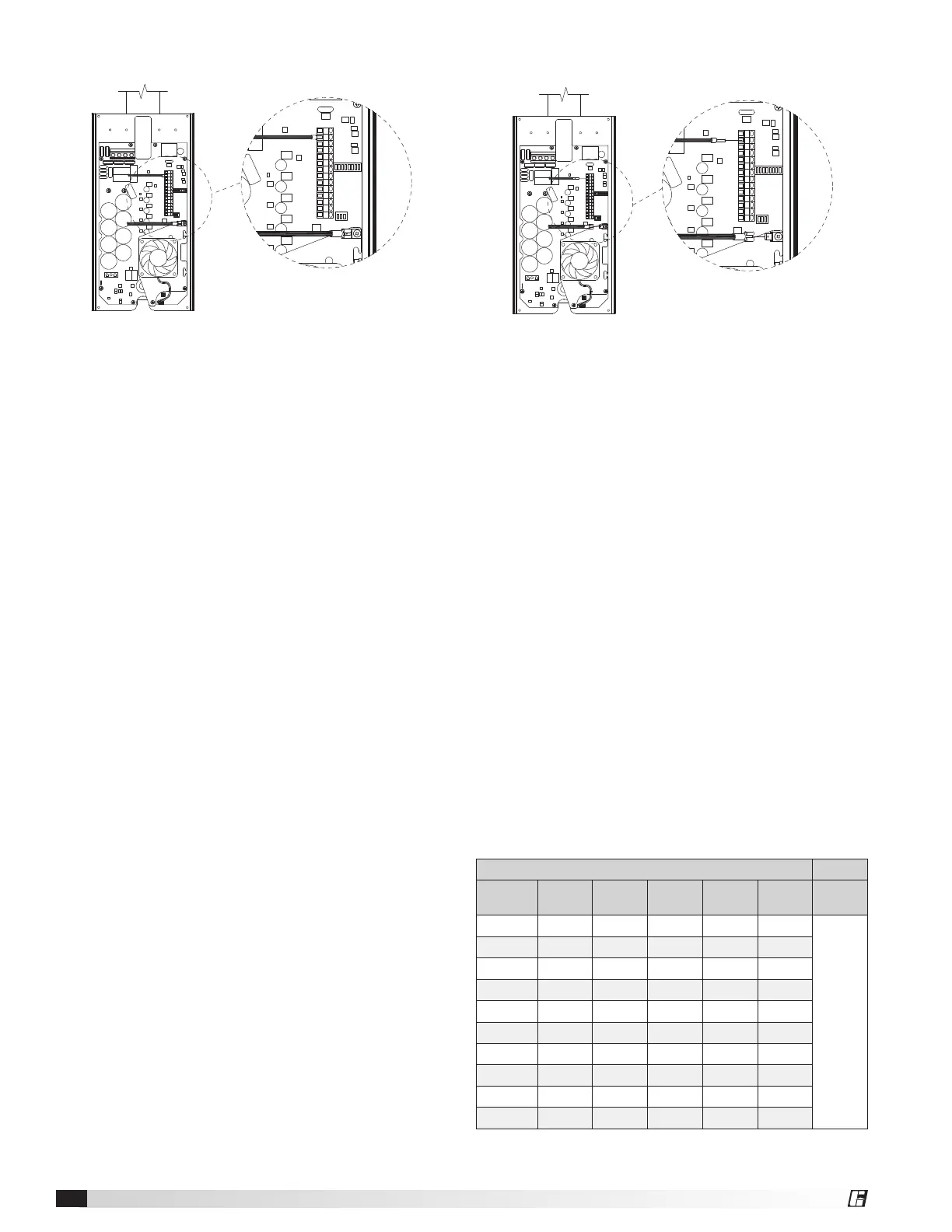
FIRST FAN IN SERIES
ALL OTHER FANS IN SERIES
1. Determine the first fan in the network daisy-chain
by identifying the fan that is connected directly to
the control source.
2. Remove the front VFD cover from the first fan in the
network using a phillips screwdriver.
3. Dipswitch 2 is used to set parameters that improve
network function. Verify that each of the switches
on dipswitch 2 are set as follows:
Position 1 – Off
Position 2 – On
Position 3 – On
4. Verify that each of the switches on dipswitch 3 are
set as follows. Positions 1 – 5 are used to set the
Modbus address of the fan and should be set as
shown below from the factory (Modbus address
#2).
IMPORTANT: Positions 6-8 are used to set parameters
needed for fan operation and should not be adjusted.
Position 1 – On
Position 2 – Off
Position 3 – Off
Position 4 – Off
Position 5 – Off
Position 6 – On
Position 7 – Off
Position 8 – Off
5. Reinstall the front VFD cover.
All Remaining Fans
FIRST FAN IN SERIES
ALL OTHER FANS IN SERIES
1. Remove the front VFD cover using a phillips
screwdriver.
2. On the communication wiring terminal strip,
remove the 24V (brown-white) wire and cap with
a wire nut or heat shrink. Additionally, remove
the drain wire that is attached to the circuit board
mounting screw and isolate from all circuit board
components using heat shrink.
3. Set dipswitch 2 as shown below. Dipswitch 2 is
used to set parameters that improve network
function and will need to be adjusted for all fans in
the network except for the first fan.
Position 1 – Off
Position 2 – Off
Position 3 – Off
4. Adjust positions 1-5 on dipswitch 3 so that each
successive fan has a unique Modbus address. A
table with possible Modbus addresses is shown
below.
IMPORTANT: Positions 6-8 are used to set parameters
needed for fan operation and should not be adjusted.
NOTE: It is good practice to use successive Modbus
addresses for networked fans, but this is not necessary
for proper functioning of the network.
5. Reinstall the front VFD cover.
Modbus Address Settings - Dipswitch 3
Modbus
Address
Position
1
Position
2
Position
3
Position
4
Position
5
Position
6, 7, 8
2 On Off Off Off Off
Do Not
Modify
3 Off On Off Off Off
4 On On Off Off Off
5 Off Off On Off Off
6 On Off On Off Off
7 Off On On Off Off
8 On On On Off Off
9 Off Off Off On Off
10 On Off Off On Off
11 Off On Off On Off
 Loading...