HVLS Standard Touchscreen Control 3
Pre-Start-Up Checks
If one control will be used to operate multiple fans,
verify that the following fan networking steps have been
completed prior to control start-up. Otherwise, turn to
page 5 to continue with control operation.
Daisy-Chain Communication Wiring
For proper network communication, HVLS fans must be
daisy-chained together using the following instructions.
NOTE: All communication wiring must be installed
in compliance with NEC 800-52 or similar. All
communication wiring needs a minimum separation of
2 inches from high voltage unless installed in separate
raceways/conduit. When possible, maintain 24 inches of
separation.
1. Connect the first HVLS fan in the daisy-chain to
the control using the shielded, twisted pair CAT-5e
communication cable that was provided with the
HVLS fan. CAT-5e cable can be plugged into any
open receptacle on the RJ45 splitter located at the
top of the fan’s downtube.
IMPORTANT: Controls and HVLS fans must be installed
with the supplied CAT-5e communication cable or
shielded, twisted pair CAT-5e (by others) that complies
with the following specifications. Cable must be twisted
pair, shielded 26 ga. CAT-5e cable with a drain wire and
must be compliant with ISO 11801. Cable must use
shielded RJ45 connectors with a soldered drain and
wiring configuration must follow EIA/TIA T568B wiring
pinout. Individual CAT-5e cable lengths must not exceed
200 ft. in order to prevent network communication
issues.
2. Plug an additional shielded, twisted pair C AT-
5e control cable into the 2-way RJ45 splitter
located at the top of the downtube on the first fan.
Connect the other end of this CAT-5e cable into the
2-way splitter on the next fan.
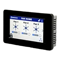
3. Repeat step 2 for subsequent fans until all fans in
the chain are connected in series, as shown in the
drawing below.
FAN 1
FAN 2
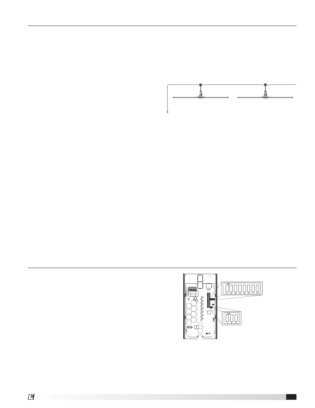
Fan Networking
If networking multiple fans to run using a single control
source, the dipswitch settings on each fan’s VFD circuit
board may need to be adjusted. Follow the instructions
on page 4 to adjust settings for the First Fan and All
Remaining Fans.
DIPSWITCH 3
DIPSWITCH 2
 Loading...