8
Installation
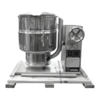
The Groen Kettle is provided with
complete internal wiring. It is ready for
immediate connection. A wiring diagram
is provided in this manual and on the
inside of the control housing service
panel. Any mechanical or electrical changes must
be approved by Groen’s Food Service Engineering
Department.
WARNING
INSTALLATION OF THE KETTLE MUST
BE DONE BY PERSONNEL QUALIFIED TO
WORK WITH ELECTRICITY. IMPROPER
INSTALLATION CAN RESULT IN INJURY
TO PERSONNEL AND/OR DAMAGE TO
EQUIPMENT.
The completed unit has been operated at the factory
to test all controls and heater elements.
1. Set the kettle in place and level it. The base
should be securely fastened to a table or work
surface. Four 3/8”-16 N.C. threaded couplings
are provided in the base of unit. Installation
under a ventilation hood is recommended.
2. Provide electrical power as specified on the
electrical information plate attached to the
equipment. Observe all local and national
codes, and all regulations in force at the time
of installation.
3. The equipment is shipped ready for three
phase operation. Refer to the wiring diagram
for single phase operation.
4. Bring the electrical service through the
entrance at the rear of the support housing,
making a watertight connection with the
incoming lines. (A BX connection is not
recommended.) Observe all local and
national codes, and all regulations in force at
the time of installation.
DANGER
ELECTRICALLY GROUND THE UNIT AT
THE TERMINAL PROVIDED. FAILURE TO
GROUND UNIT COULD RESULT IN
ELECTROCUTION AND DEATH.
5. Confirm that the jacket water level is above
mid point of sight glass. If the level is low,
follow the instructions under “Jacket Filling
and Water Treatment,” Page 14.
6. Electrically earth the unit at the terminal
provided.
7. Equipotential terminal: In accordance with
national regulations, the unit has been fitted
with an equipotential terminal.
TDB(C) ELECTRICAL SPECIFICATIONS
20 QUARTS 40 QUARTS
VOLTAGE PHASE KW AMPS KW AMPS
230 1 7.8 33 13.3` 57
400 3 7.8 11.2 13.3 19
ELECTRICAL SUPPLY CONNECTION
REQUIREMENTS
Unit TDB(C)-20 TDB(C)-40
230V - 1 Phase 33 Amps 57 Amps
400V - 3 Phase 33 Amps 57 Amps
 Loading...