English (GB)
23
2. If the light diode is flashing, the functional module is working
correctly. The fault may then be in the control panel. See
section 7.4 Replacing the control panel.
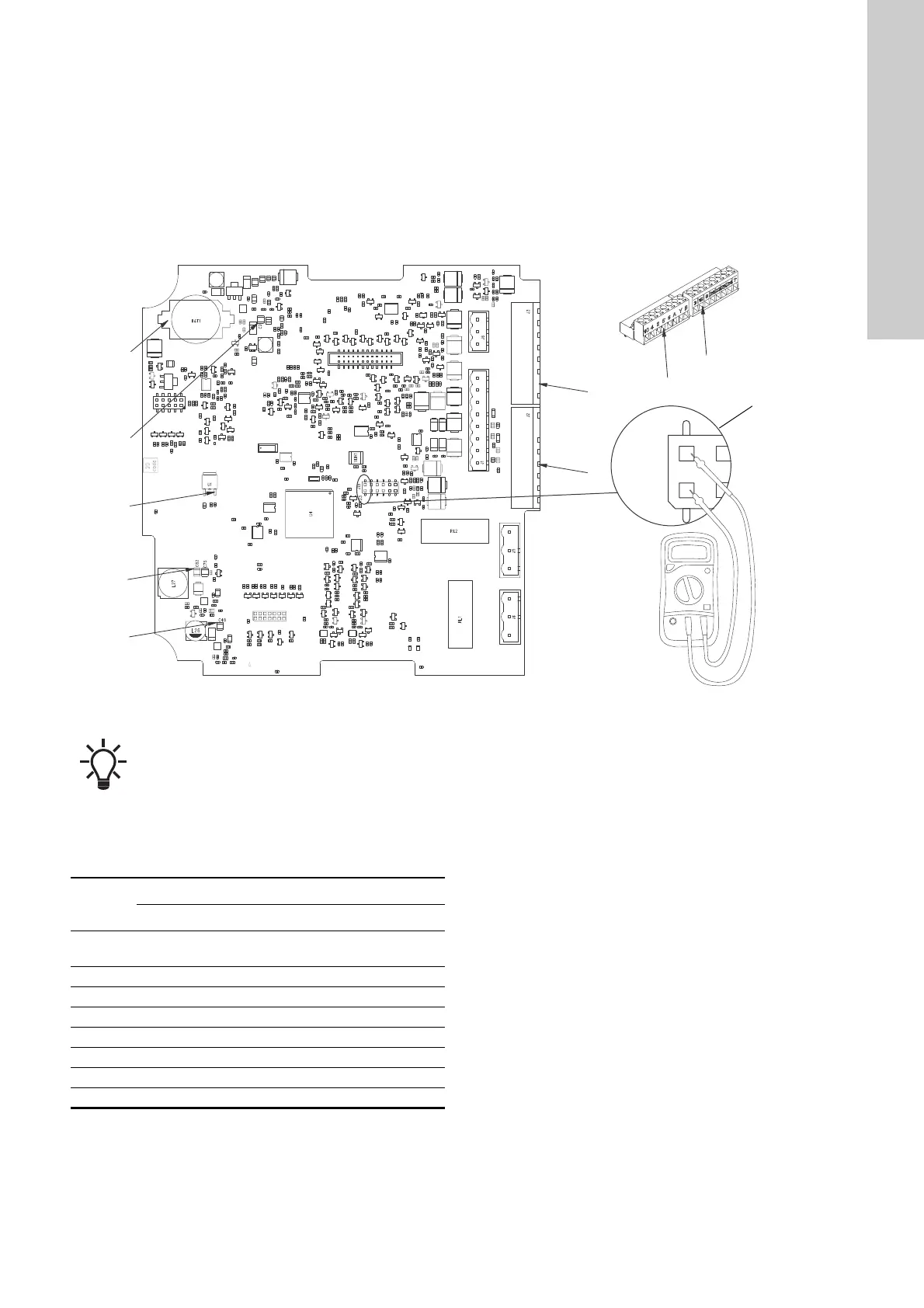
If the status diode of the functional module is off, check if the
power module supplies voltage by measuring 8.5 VDC on the
VFE plug connection between the functional module and the
power module (see fig. 54, J15). If no voltage is measured, the
connection between the modules or the power module is
defective.
If the VFE voltage to the functional module is okay, check if the
voltage between the reference point and the other measuring
points is okay. The voltage values apply to an operating motor.
Fig. 54 Measuring voltage on the functional module
To measure the voltage listed in the table below, you must use the
same reference point (ref.) seen on the figure above.
Measure the DC voltage from e.g. "ref." to "1". The measure
should be between 14.5 V and 15.7 V.
Replace the functional module if the voltage is not correct. See
section 7.7 Replacing the functional module.
TM06 7718 3816
Use a correctly calibrated measuring instrument.
Pos.
Control voltage [VDC]
Minimum Nominal Maximum
VFE
(J15)
8.5
1 14.5 15.1 15.7
2 4.8 5 5.2
3 4.8 5 5.2
4 3.2 3.3 3.4
5 23 23.9 24.8
6 4.8 5 5.2
ref. GND
 Loading...