English (GB)
26
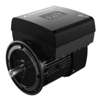
Fig. 61 Status diodes of power module, Type 1
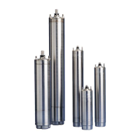
Fig. 62 Status diodes of power module, Type 2
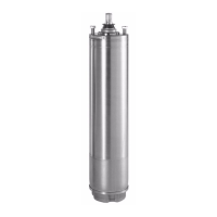
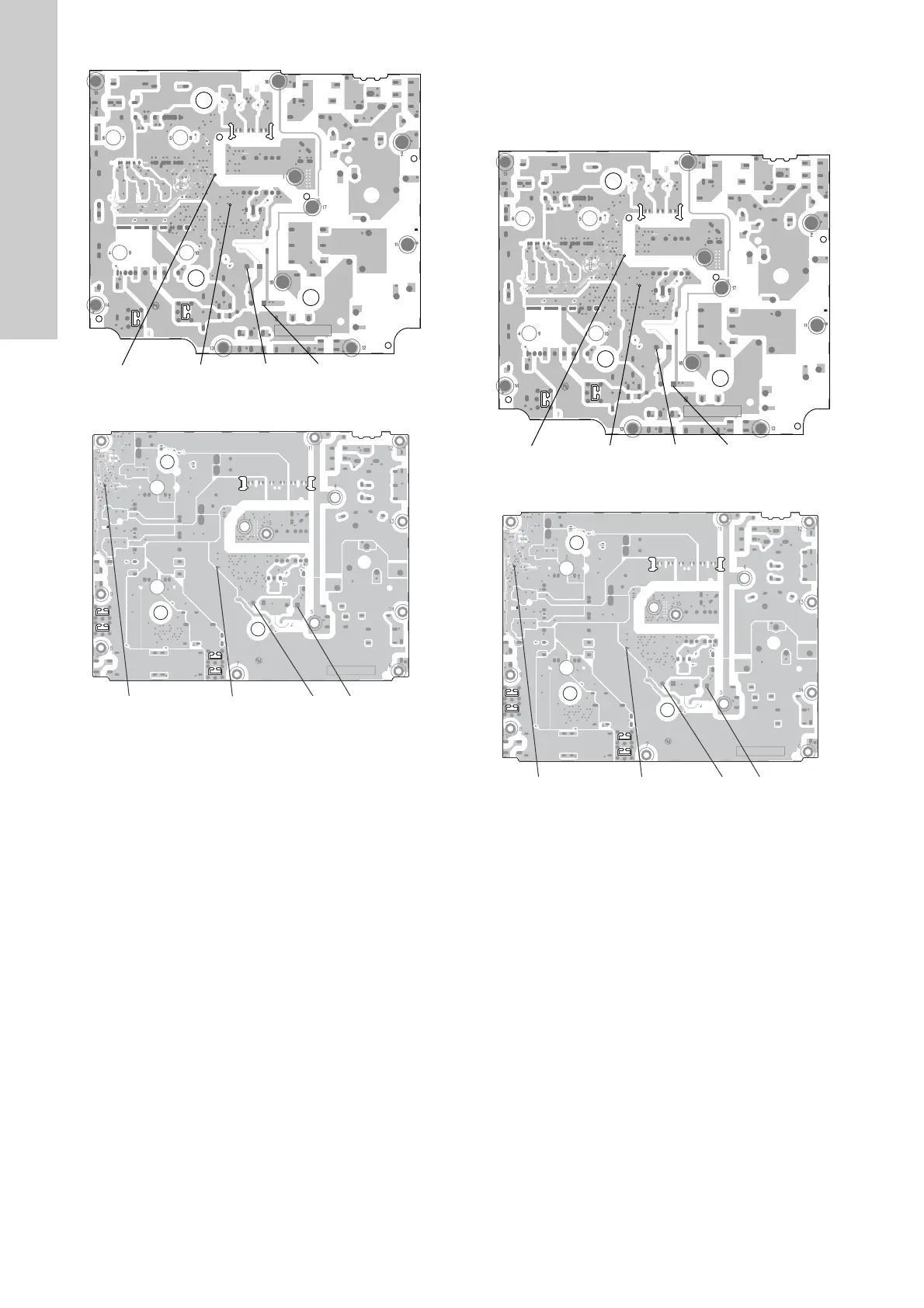
4. Measure the DC voltage across the capacitors (GND and
DC+) to ensure that the capacitors are not short-circuited. If
the function is correct, the voltage must be ≥ 566 V (at a
mains voltage of 400 V). See figures 63 and 64. If not, the
module is defective.
Fig. 63 Status diodes of power module, Type 3
Fig. 64 Status diodes of power module, Type 4
TM06 7194 3016TM06 7195 3016
LED Micro Controller LED 5V GND DC+
GND
DC+
LED Micro Controller
LED 5V
TM06 7194 3016TM06 7195 3016
LED Micro Controller LED 5V GND DC+
GND
DC+
LED Micro Controller
LED 5V
 Loading...