English (GB)
12
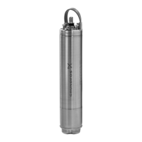
Fig. 21 Fitting the stator on the rotor
17. Unscrew the puller to slowly insert the rotor into the stator.
Press flange and stator together when the bearing (154) has
engaged with the stator housing. Check that the drain hole of
the flange faces downwards.
18. Cross-tighten the stay bolts (181). Torque: 5-6 Nm.
19. Remove the puller and fit the eye bolts (189) back on the
motor.
20. Lubricate the shafts ends.
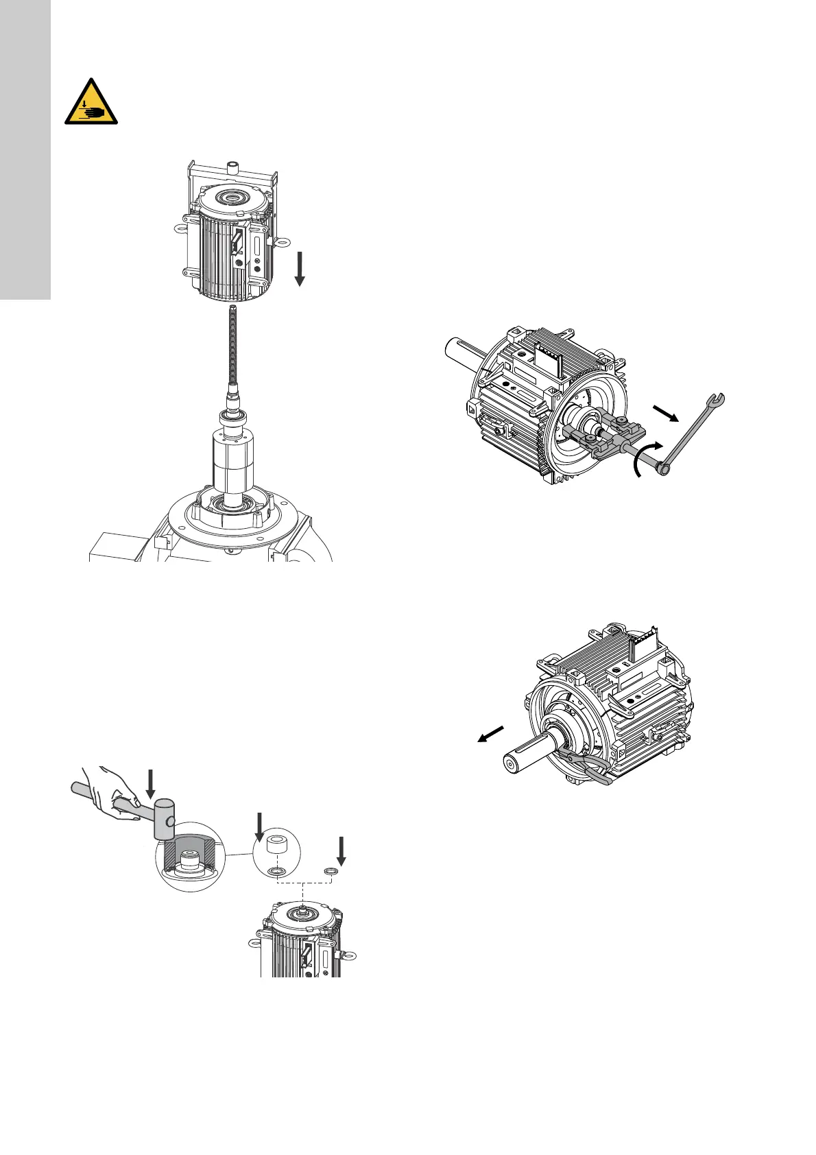
21. Fit the seal rings (156c and 156d) or the gamma rings (159d
and 159e) on the drive end and non-drive end of the shaft.
Use a punch.
Fig. 22 Fitting the seal rings or gamma rings
22. Fit the parallel key (172a) on the drive-end of the shaft.
23. Check that the shaft can rotate freely.
24. Fit the fan and cover. See section 7.11 Replacing the fan.
25. Fit the terminal box. See section 7.10 Replacing the stator
housing.
7.13 Replacing the bearings (MGE 112, 132, 160)
Dismantling
1. Disconnect the power supply.
2. Remove the stator housing from the terminal box. See section
7.10 Replacing the stator housing.
3. Remove the fan. See section 7.11 Replacing the fan.
4. Remove the parallel key (172a) from the drive-end of the
shaft.
5. Remove the gamma rings (159d and 159e) or the seal rings
(156c and 156d) from the drive end and non-drive end of the
shaft.
6. Remove the screws (206) from the non-drive end flange
(156a).
7. Remove the non-drive end flange (156a).
8. Remove the corrugated spring (158) from the non-drive end of
the shaft.
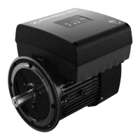
9. Remove the bearing (154) with a puller.
Fig. 23 Removing the bearing with a puller
10. Remove the screws (208) holding the bearing plate from the
drive end flange (156b).
11. Remove the screws (185) and nuts (208b) holding the drive
end flange.
12. Remove the drive end flange (156b).
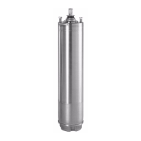
13. Remove the locking ring (188).
Fig. 24 Removing the locking ring for the bearing
14. Remove the bearing (153) with a puller.
15. Remove the bearing cover (155).
CAUTION
Crushing of hands
Minor or moderate personal injury
- Watch your fingers when you insert the rotor, as
the magnet will pull rotor and stator together with
big force.
TM06 9044 1617TM06 9044 1617
TM06 6755 1617TM06 8352 1617
 Loading...