Comparison and Test specification
Wobbulator Output
connected to
T502 (MP 503)
(II) and (III) for maximum
(IV) For symmetry
(V) for Maximum and symmetry
Filters 9 and 8 only in connection
Adjust with the ceramic oscillator.
b) AM 2,46 MHz-Oszillator
K2-6 turned ON
Signal Generator
coupled to
(VII) Visually to center of C 459
(VI) for maximum
(VII) Fine adjustment C 459
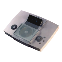
The notes marked with numbers refer to the expansion sketch embossed
in the bottom of the housing.
a) Pull out the mains cable connector and remove any batteries or the
rechargeable batteries that may have been inserted.
b) Remove the grip shell after loosening the 2 Phillips screws (1), (2).
c) remove the back panel (3).
d) Unsolder the connections of the two loudspeakers, pull off the antenna
cable and unplug the plug connection to the mains transformer.
e) Pull off the knobs and unscrew the 6 nuts of the controller units
(potenciometers) (4).
f) Release the four latches (5), (6), (7), (8) and remove the chassis from the
housing.
Alignment Instructions
All the voltages must be adjusted with the aid of sufficiently accurate
instrument (e.g. GRUNDIG DM 44), and the given voltages should be kept
within the stated tolerances.
I. Adjustment of the Operating Points
No signal, AM button pressed, range switch on KW1 U8 = 9V:
1. Adjust the emitter current of T 502 with R 504 so that the voltage drop
across R506 is 1.3V
2. The control voltage at PIN 9 of IC 401 is set to 0.15V with the
resistance controller R 409. An analogue measuring device (e.g.
GRUNDIG UV 5 A) should be used.
3. With the BFO/SSB section switched ON, adjust the trimmer
resistor R 703 so that the voltage drop across R704 is 4V.
4. UB = 7.2V:
At a voltage of 7.2 V, set the display instrument to the battery check
position with the R 658 controller so that the deflection of the
instrument is on the Dryfit Accu-mark.
II. Adjusting the Charging Voltage UL
With a mains supply of 220V AC and the receiver switched OFF, the
charging voltage UL is to be measured with an equivalent resistance
of 1 kohm and an electrolytic capacitor of 1000 uF (connect in
parallel to the charging contact and minus), the nominal value of
which should be between 9.05 and 9.35 V.
With a voltage of UL < 9.05 V, R 653 (connect separating point X)
must be connected, with a voltage of UL > 9.35 V, R 654 (connect
separating point Y) must be switched on.
III. Frequency Counter
Feed in 32.000MHz/80 mV to St V802 (3) and 2.460 MHz/50 mV to St
V 802 (1) and with C0811 set the display to 30.000 MHz.
Mod. frequency <1000 Hz
1. AM.IF
a) AM-IF Alignment 460kHz