EasyManua.ls Logo

Haier 2U14CS2ERA User Manual

Haier 2U14CS2ERA
80 pages
To Next Page IconTo Next Page
To Previous Page IconTo Previous Page
Page #28 background imageLoading...
Page #28 background image
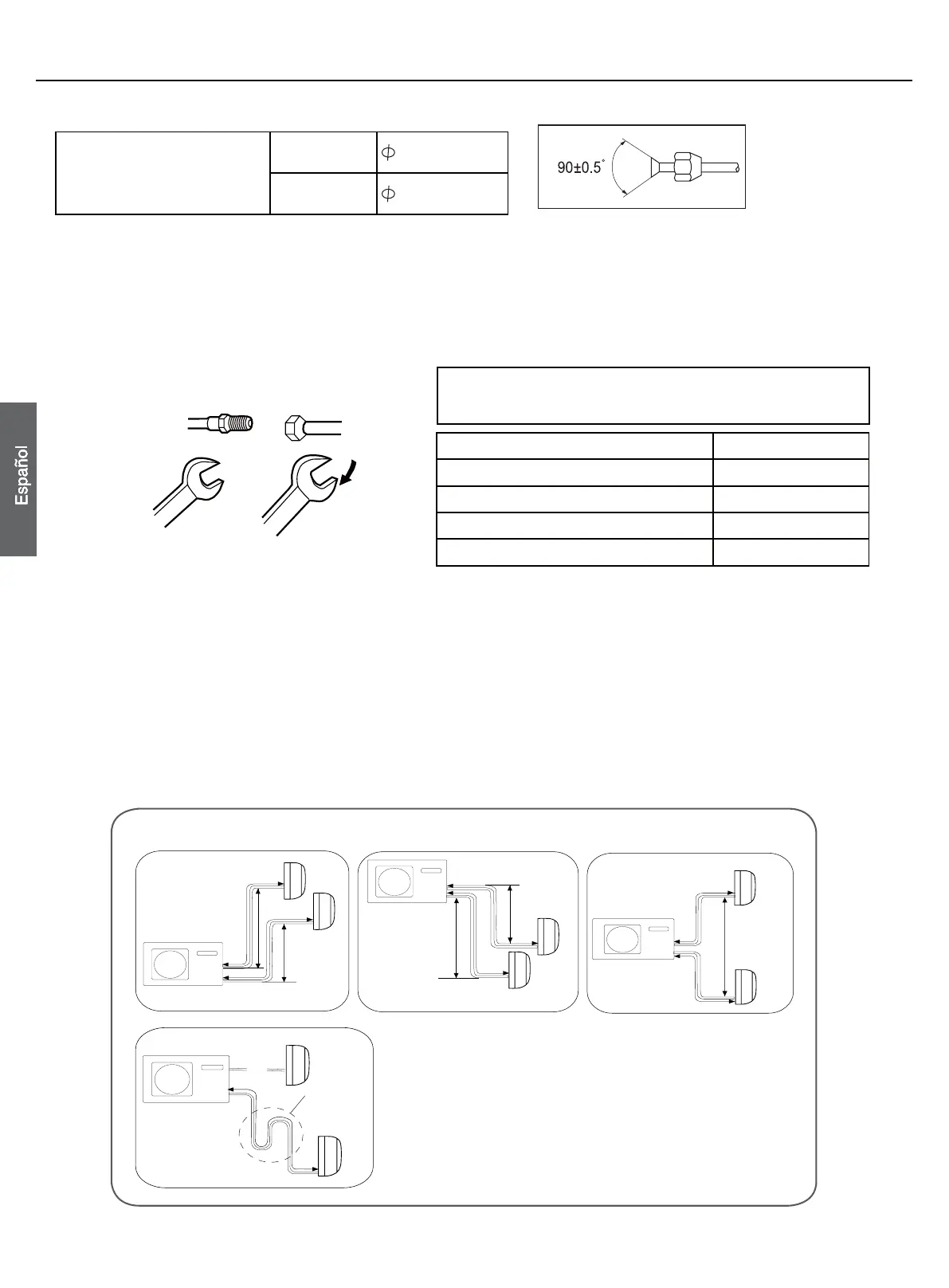
Ɣ Inserte las tuercas cónicas retiradas en los tubos que se
van a conectar y, a continuación, abocarde los tubos.
Si se fuerza la ¿MDFLyQ sin aplicar centrado podrían
dañarse los tubos y provocarse una fuga de gas.
Media unión Tuerca cónica
Llave Llave dinamométrica
Diámetro del tubo (ø) Par de apriete
Lado de líquido 6,35 mm (1/4") 18N.m
Lado de líquido/gas 9,52mm (3/8") 42 N.m
Lado de gas 12,7mm (1/2") 55 N.m
Lado de gas 15,88 mm (5/8") 60 N.m
Procedimiento instalación
Conexión de los tubos
1. Tamaño de los tubos
2U14CS2ERA
2U18FS2ERA
Tubo de líquido
6,35x0,8 mm
Tubo de gas
9,52x0,8 mm
2
. Conexión de los tubos
Ɣ Para doblar un tubo, intente hacer la curva lo más suave posible para no aplastar el tubo. El radio de
doblado
debe ser de entre 30 y 40 mm o superior.
Ɣ Será más sencillo conectar en primer lugar el tubo de gas.
Ɣ El tubo de conexión es especial para el tipo R410A.
Procure que no penetren materiales, como residuos de arena, agua, etc., en el tubo.
PRECAUCIÓN:
Procure que no penetren materiales, como residuos o arena, en el tubo. La longitud estándar del tubo es
de 5m. Si la longitud total del tubo es superior a 20m, se verá afectado el funcionamiento de la unidad, y
deberá cargarse el refrigerante a razón de 20 g/m. No obstante, la carga de refrigerante deberá ser
realizada por un ingeniero profesional en aire acondicionado. Antes de añadir refrigerante adicional,
realice una purga de aire desde los tubos refrigerantes y la unidad interior utilizando una bomba de vacío
y cargue después el refrigerante adicional.
B
A1
B1
A2
B2
B1
B2
A3
A1
B1
A2
B2
Unidad interior
Unidad exterior
Unidad interior
Filtro de
aceite
Ɣ Elevación máx. A1 máx =15 m A2 máx =15 m
A3 máx =15 m
Ɣ En caso de que la elevación A sea superior a 5 m, el ¿OWUR
de aceite debe instalarse cada 5 ~7 m.
Ɣ Longitud máx.: B1 máx. de 20m B2 máx. de 20m
(B1+B2) máx de 30m
Ɣ En caso de que la longitud total del tubo (B1+B2) sea
superior a 20 m, deberá cargarse el refrigerante a razón
de 20 g/m.
Unidad
interior
Unidad exterior
PRECAUCIÓN
Unidad interior
Unidad exterior
Unidad
interior
Unidad exterior
Unidad interior
Unidad
interior
24

Questions and Answers:

Haier 2U14CS2ERA Specifications

General IconGeneral
BrandHaier
Model2U14CS2ERA
CategoryAir Conditioner
LanguageEnglish

Summary

European Regulations and Important Information

European Regulations Conformity

Details compliance with CE, RoHS, and WEEE directives for product conformity.

Disposal Requirements

Instructions for proper disposal of electrical and electronic products according to WEEE directive.

Refrigerant Information

Important details on the refrigerant used, including Kyoto Protocol compliance and handling.

Installation Drawings

Indoor/Outdoor Unit Installation Drawings

Visual guide for installing indoor and outdoor units, including piping and placement.

Optional Parts for Piping

Lists and illustrates optional parts required for the piping installation process.

Outdoor Unit Fixing and Dimensions

Instructions on how to fix the outdoor unit and its detailed installation dimensions.

Safety Precautions - General

General Safety Warnings and Symbols

Critical warnings, cautions, and symbols to ensure safe operation and prevent hazards.

Handling Precautions

Guidelines on unit installation, modification, and handling to avoid risks like shock or fire.

Safety Precautions - Unit Specific

Unit Handling and Modification Warnings

Further warnings on unit handling, modification, and specific safety measures.

Refrigerant Leak and Exposure Precautions

Safety measures concerning refrigerant leaks and exposure to heat sources.

Safety Precautions - Refrigerant and Location

R410A Refrigerant Handling

Specific safety measures for handling R410A refrigerant and associated tools.

Installation Environment Precautions

Precautions for installation location, unusual environments, and hospital settings.

Safety Precautions - Electrical and Test

Electrical Work and Grounding

Safety guidelines for performing electrical work, grounding, and using circuit breakers.

Test Run Safety

Safety measures to be followed before and during the test run of the unit.

Before Installation Procedures

Items to Check and R410A Tools

Lists essential checks and necessary tools for installation, distinguishing R410A specific items.

Necessary Tools and Materials

Comprehensive list of tools and materials required for installation and servicing.

Piping and Flare Machining

Piping Materials and Radial Thickness

Details on copper pipe specifications, radial thickness, and type requirements.

Flare Machining Dimensions

Specific dimensions for flare machining for R410A units to ensure better air tightness.

Flare Nut Specifications

Information on the type and dimensions of flare nuts used for R410A connections.

Pre-Installation Tests and Procedures

Air Tightness Test

Procedures for performing an air tightness test, including pressure checks.

Vacuuming Procedures

Detailed steps for vacuumizing the system using a vacuum pump and gauge.

Refrigerant Charging and Leak Remedies

Guidelines on charging refrigerant and measures to take in case of leaks.

Installation Procedure - Outdoor Unit

Accessories and Site Selection

Details on required accessories and criteria for selecting the outdoor unit installation site.

Outdoor Unit Installation and Dimensions

Steps for installing the outdoor unit on a foundation and its installation dimensions.

Installation Procedure - Piping

Piping Size and Connection

Specifies pipe sizes for liquid and gas lines and provides guidance on connecting pipes.

Pipe Bending and Torque

Instructions on bending pipes and applying correct fastening torque to prevent leaks.

Installation Procedure - Air Tightness

Air Tightness Test Method

Explains the method for conducting the air tightness test using a nitrogen tank and pressure monitoring.

Leak Checking

How to identify and fix leaks during the air tightness test.

Installation Procedure - Vacuuming

Vacuum Pump Usage

Detailed steps for using a vacuum pump with a gauge manifold for system evacuation.

Refrigerant Charging Precautions

Warnings and cautions regarding refrigerant charging and preventing system contamination.

Installation Procedure - Electrical Wiring

Electrical Wiring Precautions

Safety guidelines for performing electrical wiring work.

Power Supply and Interconnecting Wires

Guidance on selecting appropriate wire sizes and circuit protection.

Wiring Procedure

Step-by-step instructions for connecting electrical wires to the unit.

Outdoor Unit Troubleshooting

Test Run Preparation

Pre-operation checks and preparations before conducting the test run of the unit.

Troubleshooting Guide

A guide to diagnose and resolve common issues based on LED flashes and trouble descriptions.

Related product manuals