OUTDOOR TECHNICAL OVERVIEW
B-2
ENGLISH
Topic TitleComponents
2
4
3
1
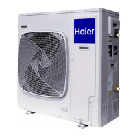
The SMB is connected to the PCB via connections CN-2 and CN-3.
The SW1 DIP switches are OFF (default position for normal operation).
The digital display will indicate operating frequency of the compressor when
no error code is present, or will ash an error code if present.
A solid green LED indicates that the A, B, C, D or E unit is successfully
communicating with the outdoor unit.
The SMB has important features including operational DIP switches, error code display, compressor speed, and diagnostic
capabilities.
2
4
1
3
Service Monitor Board (SMB)
The outdoor unit features a variable speed rotary type compressor that delivers refrigerant ow to up to 4 individual indoor units.
The system uses R-410A refrigerant mixed with PVE oil. The system is rated to operate at 208/230 volts single phase 60 Hz
power.
Indoor units compatible with this model include high wall type, slim duct type and cassette type.
The indoor cassette unit can be controlled by either a remote control or a wired controller. The indoor high wall unit is controlled
by infrared remote. The slim duct unit is controlled by wired controller only.
All indoor units must operate together in either heat mode, or cool mode. The indoor units will not automatically switch between
heat and cool modes of operation. The rst unit that is turned on and set to provide comfort, will set the operating mode of the
system. All other indoor units must now operate in the same mode as the rst unit that was energized.
2
4
5
6
3
1
1
2
6
3
4
5
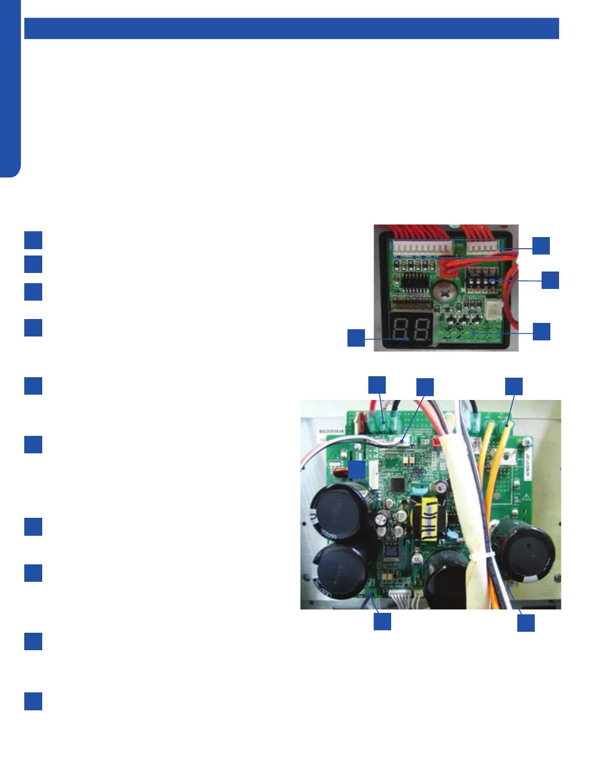
The Module Circuit Board generates 3 phase DC power to
operate the variable speed compressor. The compressor
is connected to the MCB via terminals CN-5. CN-6 and
CN-7.
A Reactor Coil is connected to the MCB at terminals CN-3
and CN-4. The Reactor Coil will lter out electrical noise
generated at high frequency operation. The ltering out
of electrical noise will prevent pin holes from being burned
into the compressor motor windings during high speed
operation.
The MCB has 3 surface mounted LED indicators to aid
in diagnostics. The indicator LED colors are GREEN for
Power/Status, Red and Yellow for Diagnostic Codes.
The MCB generates heat that is transferred to a heat sink
located on the back of the board. The heat sink transmits
this heat to the outdoor air. A temperature sensor Tm
is attached to the inverter semi-conductor chip on the
reverse side of the board.
The temperature sensor is connected to the MCB via
terminal CN-11. If excessive heat is detected by this sensor, the system will stop operation and generate an Error Code 38.
The RED Diagnostic LED indicator located on MCB will ash 14 times. When the sensor cools o, the system will re-start
and the diagnostic error codes will clear.
There is a communication cable connected to the MCV via Plug CN-9. The wire from this plug goes to a connection on the
ECU board. If this plug is disconnected or loose, the RED Diagnostic LED located on the MCB will ash 14 times and the
system will shut o on an Error Code 04.
Module Circuit Board (MCB)
 Loading...