Printed circuit board connector wiring diagram
11 Domestic air conditioner
6.Printed circuit board connector wiring diagram
Connectors
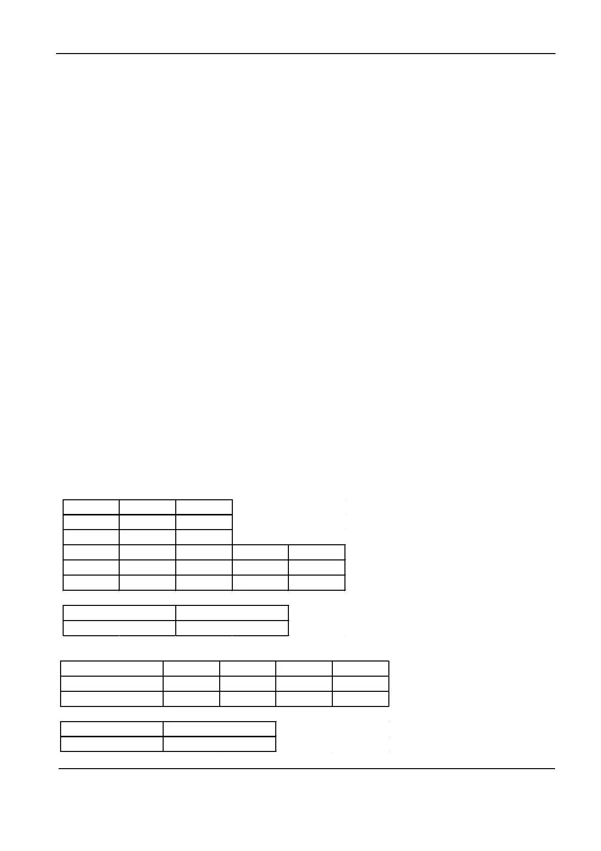
PCB(1) (Control PCB) For AS35TAMHRA-C
J2 OFF ON OFF ON
DISPLAY SERIES
3 2 5 /7 9 8/498 324 387/1045 317
UNIT MODEL
OFF ON
1 A B
2 N_RC RC
3 ON ON OFF OFF
4 ON OFF ON OFF
PCB 35 33 26 23
AS35TAMHRA-C
AS35TAMHRA-C
) CN9&CN8 Connector for AC fan motor
) CN6 Connector for heat exchanger thermistor and Room temperature thermistor
) CN5’ Connector for UP&DOWN STEP motor
) CN17 Connector for indoor terminal L
) CN21 Connector for indoor terminal N
) CN7 Connector for display board
) CN23 (red line) Connector for communicate between the indoor board and the outdoor board
) CN34 Connector for wifi Module
) CN51 Connector for room card
0) CN36 Connector for Remote control
1 ) CN2 Connector for Wired Controller
ote: Other designations
CB(1 ) (Indoor Control PCB)
) SWI Connector for Forced operation ON / OFF switch
) FUSE1 Fuse 3.15A/250VAC
 Loading...