F
A
C
E
D
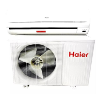
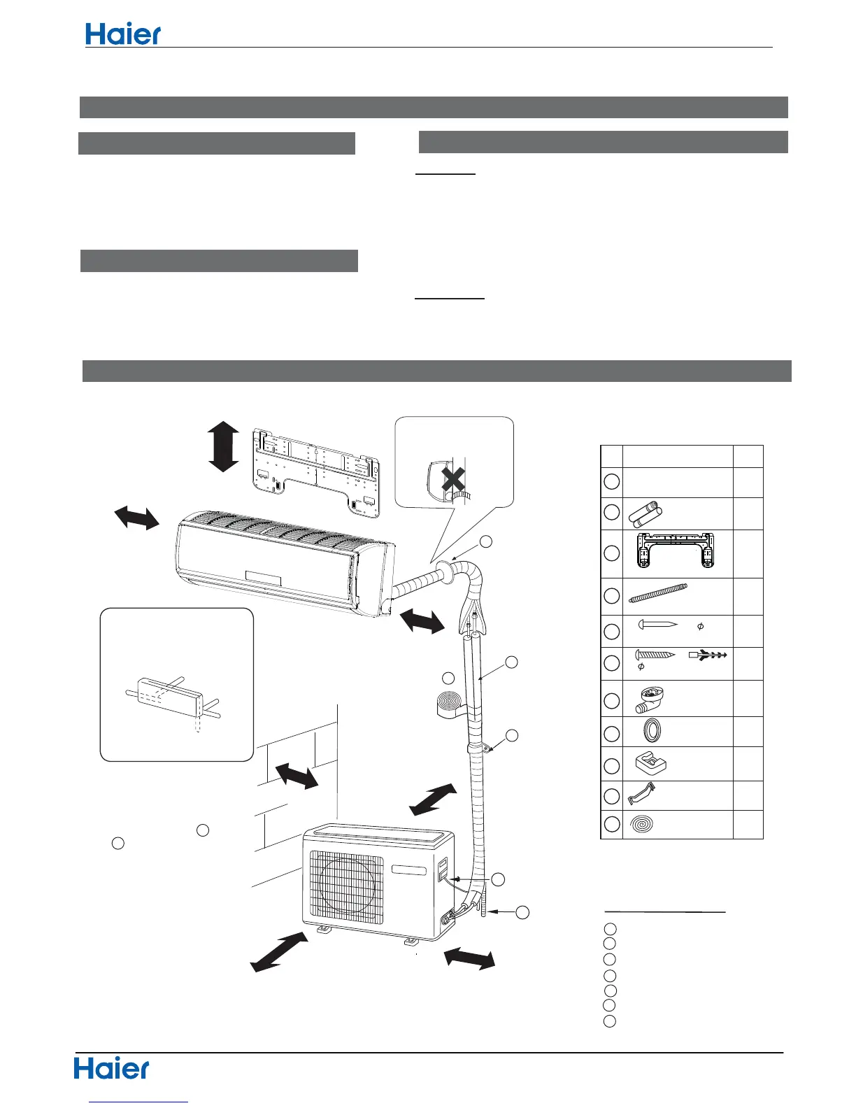
Drawing for the installation of indoor and outdoor units
Optional parts for piping
Non-adhesive tape
Adhesive tape
Saddle (L.S) with screws
Connecting electric cable
for indoor and outdoor
Drain hose
Heating insulating material
Piping hole cover
The marks from to
in the figure are the
parts numbers.
The distance between
theindoorunitandthe
floor should be more
than 2m.
ThemodelsadoptHFCfreerefrigerantR410A
more than
10cm
more than 5cm
more than 10cm
more than 10cm
more than
10cm
more than15cm
more than
60cm
A
G
ƽ
ƽ
Necessary Tools for Installation
Driverƽ
Torque wrench
ƽ
(17mm,22mm,26mm)
Nipperƽ
Reamerƽ
Hacksawƽ Pipe cutterƽ
Gas leakage detector orƽ
soap-and-water solution
Hole core drillƽ Flaring toolƽ
Spanner(17,19 and 26mm)ƽ Knifeƽ
Measuring tapeƽ
Indoor Unit
Place, robust not causing vibration, where the body can be supported sufficiently.ƽ
Place, not affected by heat or steam generated in the vicinity, where inlet and outlet of the
unit are not disturbed.
ƽ
Place,possibletodraineasily,wherepipingcanbeconnectedwiththeoutdoorunit.ƽ
Place,wherecoldaircanbespreadin a roomentirely.ƽ
Place, nearby a power receptacle, with enough space around. (Refer to drawings).ƽ
Place where the distance of more than lm from televisions, radios, wireless apparatuses
and fluorescent lamps can be left.
ƽ
In the case of fixing the remote controller on a wall, place where the indoor unit can
receivesignalswhenthefluorescent
ƽ
lampsintheroomarelightened.
Outdoor Unit
Place, which is less affected by rain or direct sunlight and is sufficiently ventilated.ƽ
Place, possible to bear the unit, where vibration and noise are not increased.ƽ
Place, where discharged wind and noise do not cause a nuisance to the neighbors.ƽ
Place, where a distance markedƽ
isavailableasillustratedintheabovefigure.
Before inserting power plug into receptacle, check the voltage without fail.
The power
sourceisthesameasthe
ƽ
correspondingnameplate.
Install an exclusive branch circuit of the power.
ƽ
Areceptacleshallbesetupin a distancewherethepowercablecanbe
reached.
Donotextendthecablebycuttingit.
ƽ
Selection of Installation Place
Power Source
A
F
C
E
D
G
B
Arrangement of piping
directions
Rear left
Left
Rear
right
Right
Below
G
Preparation
Please be subject to the actual product purchased , the above picture is just for your reference.
Attention must be paid to
the rising up of drain hose
Read this manual before installation
Explainsufficientlytheoperatingmeanstotheuseraccordingtothismanual
No. Accessory parts
Remote controller
R-03 dry battery
Mounting plate
Drain hose
Steel nail, cement
Screw
Plastic cap
Drain-elbow
Cover
Cushion
1
1
2
3
4
5
6
7
8
9
10
2
1
1
6
4
1
1
4
1
Number
of
articles
Accessory parts
4X50
4X25
Pipe supporting plate
11
Connecting cable
1
Note:Cooling only units don't have
Drain-elbow
Functions and Control
8.Installation Manual of Room Air Conditioner
61
Domestic Air Conditioner
 Loading...