1
2
3
4
5
6
7
8
4
LO MED HI
Operation mode
AUTO FANCOOL DRY
Remote controller
HEAT
1
2
3
4
5
9
10
11
12
13
14
15
16
17
22
23
24
25
19
20
21
8
18
7
6
AUTO
Display
circulated
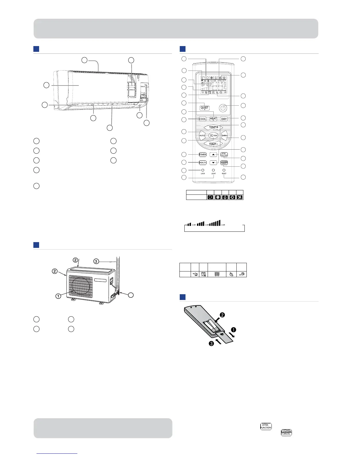
1
Inlet
2
Inlet grille
3
Outlet
4
Vertical blade
(adMust left and right air ÀoZ)
5
Hori]ontal Àap
(adMust up and doZn air ÀoZ.
Don¶t adMust manuall\.)
1
Outlet
2
Inlet
6
Displa\ board
7
Emergenc\ SZitch
8
Air Purif\ing Filter
(inside)
3
Connecting piping and electrical Ziring
4
drain hose
Operation
mode QUITE SLEEP
Supplemented
electrical heating
(not used) HEALTH POWER
Remote
controller
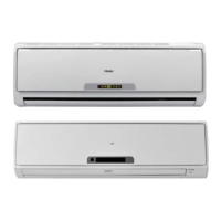
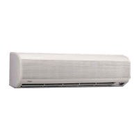
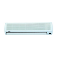
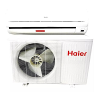
Parts and functions
Indoor Unit
Outdoor Unit
Loading of the battery
Remote controller
The picture aboYe is for reference products ma\ differ slightl\
from the image shoZn.
1. Mode displa\
HEALTH function is not aYailable for some units.
The picture aboYe is for reference onl\. Products ma\ differ
slightl\ from the image shoZn.
Hint:
RemoYe the batteries if the product Zon¶t be in use for a long period. If there
is an\ displa\ after the batteries are remoYed Must press the reset Ne\.
Note:
The distance betZeen the signal transmission head and the receiYer hole
should be less than 7m. An\ obstacles betZeen the transmission head and
receiYer hole ma\ blocN the signal.
If an electric Àuorescent light or Zireless telephone is installed in the room it
ma\ interrupt the signal so the distance betZeen the controller and indoor unit
should be shorter.
If the displa\ is full or unclear charge the batteries.
If the remote controller doesn¶t run normall\ remoYe the batteries and reload
seYeral minutes later.
If tZo units are installed in the same room both units can be operated b\
one remote controller. <ou can also maNe a dedicated remote controller for
each unit. The remote controller and unit are b\ default set as ID codes ³A´
shoZn on the top left hand side of the displa\. To change ID for the unit
and remote turn the poZer on and press the
button repeatedl\
until ³AB´ is displa\ed ± the ³B´ should be Àashing. Press
button
to con¿rm. ³B´ should noZ be shoZn on the displa\.
1. RemoYe the batter\ coYer
2. Load the batteries as illustrated.
Use ³AAA´ batteries resetting
Ne\ (c\linder)
3. Be sure that the batteries
are in line Zith the / -
4. Load the batter\ then
replace the coYer.
2. Signal sending displa\
3. SWING displa\
4. FAN SPEED displa\
5. LOCK displa\
6. TIMER OFF displa\
TIMER ON displa\
7. TEMP displa\
8. Additional functions displa\
. QUIET button
10. HEAT button
11. COOL button
12. AUTO button
13. FAN speed button
14. TIMER button
15. HEALTH button
16. LOCK button
Used to locN buttons
and LCD displa\.
17. LIGHT button
Turns the indoor LED displa\
board on and off.
18. POWER ON/OFF button
1. DR< button
20. TEMP button
21. SWING button
22. HOUR button
23. E;TRA FUNCTION button
Functions:
FAN onl\ mode
AirÀ
oZ position 1/2
AirÀoZ position 4/5
Restore original louYer position
Right / Left airÀoZ (not used)
A-B
remote selection
Heating mode
SLEEP mode
Electrical element heating
(not used)
Refresh air (not used)
POWER operation
Fahrenheit / Celcius displa\
24. CONFIRM/CANCEL button
Function: Set and cancel the timer
and other additional functions
(press Zithin 5 seconds to con¿rm).
25. RESET button
When the remote controller
appears abnormal use a sharp
pointed article to press this button
to reset the remote.
1
 Loading...