2.Thewiringmethodshouldbeinlinewiththelocalwiringstandard.
3. After installation, the power plug should be easily reached.
4. A breakershouldbeincorporatedintofixedwiring.Thebreakershouldbe
all-pole
switch.
Outdoor unit
Install according to Drawing for the installation of indoor and
outdoor units
ƽ
and the bending radius should be 30 (1 1/6) to 40
mm (1 4/7) or longer.
Connecting the pipe of gas side first makes working easier.
ƽ
TheconnectionpipeisspecializedforR410A.ƽ
Installation of Outdoor Unit
Half union
Flare nut
Torque wrench
The standard pipe length is 7m (27 9/16) . If it is over 7m (27 9/16) , the function
oftheunitwillbe
affected.Ifthepipehas tobelengthened,therefrigerantshould
be charged,
accordin
g to 20 g/m (0.018 oz/inch)
.Butthec
harge of refrigerant must
be conducted by professional air conditioner servicer. Before adding additional
refrigerant, perform air
purging from the refrigerant pipes and indoor unit using
a v
acuum
pump,then
Spanner
Forced fastening without careful centering may
damage the threads and cause a leakage of gas.
Pipe Diameter(ǿ) Fastening torque
Liquid side6.35mm(1/4") 18N.m/13.3Ft.lbs
Liquid/Gas side9.52mm(3/8") 42 N.m/30.1Ft.lbs
Gas side 12.7mm(1/2") 55N.m/40.6Ft.lbs
Gas side 15.88mm(5/8") 60 N.m/44.3Ft.lbs
Connection of pipes
charge additional refrigerant.
Outdoor unit
Indoor unit
A
B
Outdoor unit
Indoor unit
A
B
A
B
Outdoor unit
Indoor unit
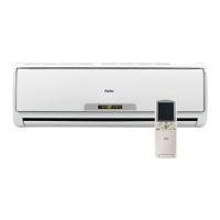
Oil trap
CAUTION
Max.Elevation: Amax=1m
●
In case the elevation A is more●
than 5m, oil trap shoud be
installed every 5~7m
Max. Length: Bmax=15m
●
Incasethepipelength B is●
more than 10m, the refrigerant
should be charged, according
to 20 g/m.
3
Connection
If the drain-elbow is used,ƽ
please attach it as figure. (Note:
Onlyforheatpumpunit.)
1.
Open the handle on low side of manifold and
2.
operate vacuum pump. If the low
3.
After the
completion of vacuuming, close the
handle ‘Lo’ in gaugemanifold and
stop the operation of the vacuum pump.
Attaching Drain-Elbow
PurgingMethod:Tousevacuumpump
Open the valve rod stem the 2-way valve counterclockwise to 90 degrees.4.
After 6 seconds, close the
2-way valve and inspect for
gas leakage.
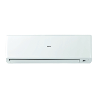
Power cable:
HSU12VHJ(DB)-W
Outdoor unit
3
2
^
Power
Wiring
1
)
(
N
)
(L
)
(
C
3
2
1
)
(
N
)
(
L
)
(
C
Indoor unit
Power cable:
ƽ
ƽ
ƽ
ƽ
ƽ
ƽ
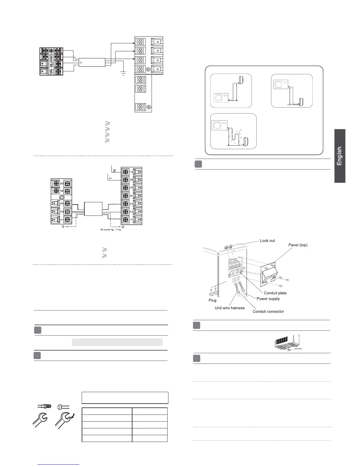
Take off the panel(top), by removing the 5 screws.
Remove the plugs on the conduit plate.
Temporarily mount the conduit tubes on the conduit plate.
Connect both the power supply and unit wire harness to
the corresponding terminals on the terminal board.
Ground the unit in accordance with local codes.
Allow several extra inches of wire for making wiring
connections.
Use lock nuts to secure conduit tubes.
ƽ
To bend a pipe, be careful not to crush the pipe,
HSU09VHJ(DB)-W
HSU24VHJ(DB)-W
HSU18VHJ(DB)-W
HSU12XCK-W
HSU09XCK-W
Power cable:
Power cable:
Power cable:
Power cable:
1. If the fuse on PC board is broken please change it with the
type of
T. 3.15A/250V(indoor unit),25A/250V(outdoor unit).
4wire 18AWG
2wire with ground 16AWG
2wire with ground 16AWG
2wire with ground 12AWG
2wire with ground 12AWG
2wire with ground 16AWG
2wire with ground 16AWG
Outdoor unit
Indoor unit
Remove the service port cap of the 3-way valve and the valve stem cap for both
valves. Connect the low pressure hose from the manifold set to the 3-way valve.
Connect the center hose to the vacuum pump.
side gauge reaches a vacuum immediately, ensure the hoses are connected
properly and the low side manifold handle is open.
Vacuum for a minimum of 15 minutes and check the gauge for a proper vacuum.
Leave the hoses connected and check
the vacuum level again in 1-2 minutes. If you lose the vacuum, ensure all
connections are tight and flare the tubes again if needed.
Ensure that no dirt or debris enters the pipe.
Control Wiring
All models: Control cable: 4wire, 18AWG
 Loading...