9
HAMPTONBAY.COM
Please contact 1-877-527-0313 for further assistance.
Assembly - Hanging the Fan (continued)
1 2 3 4
ON DIP
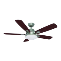
Setting the remote control codes
6
NOTE: The frequencies on your receiver and remote control have
been preset at the factory. Before installing the receiver, make
sure the dip switches on the receiver and remote control are set
to the same frequency. The dip switches on the remote control
are located inside the battery compartment.
To set the code on the remote control:
□ Remove the battery cover by pressing rmly on the arrow
and sliding the cover off.
□ Slide the code switches to your choice of either up or down.
The factory setting is up.
□ Install a 9-V battery (included) into the remote control.
□ Replace the battery cover on the remote control.
To set the code on the receiver:
□ Slide the code switches to the same position as set on your
remote control.
Controller Model: FAN-18R
NOTE: This remote is equipped with a 16-code combination.
To prevent possible interference from or to other remote units,
such as garage door openers, car alarms, or security systems,
change the combination code, but be sure that the code on
both the hand held transmitter and receiver in the fan are the
same.
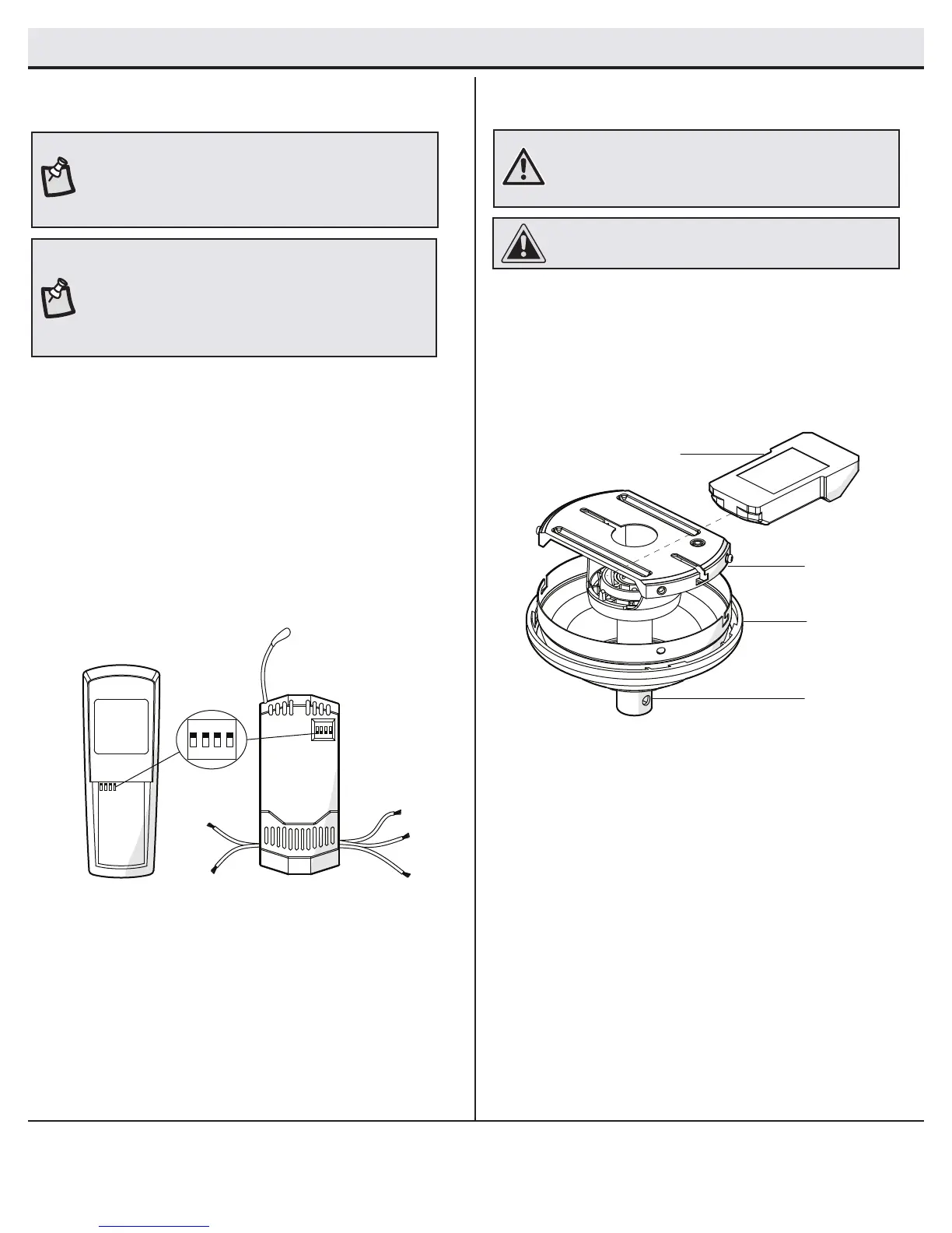
Installing the receiver
□ Position the remote control/receiver (K) at side up and per-
pendicular to the slide-on mounting bracket (A).
□ Position the supply wires to the left side of the slide-on mount-
ing bracket (A), and position the fan wires to the right side.
□ Partially insert the remote control/receiver (K) at side up until
one end rests on the ball/downrod assembly (B).
7
WARNING: To reduce the risk of re or electric shock,
remember to disconnect power. The electrical wiring must
meet all local and national electrical code requirements. The
electrical source and fan must be 110/120 volt, 60Hz.
CAUTION: If other fan wires are a different color, have this unit
installed by a licensed electrician.
A
B
K
C
 Loading...