REAR-PANEL CONNECTIONS
7
•
∞
¶
⁄
fi
ª
¡
£
‹
°
b
d
g
j
i
a
™
¢
§
‚
¤
›
fl
‡
·
c
e
f
h
k
31
1
35135
(
100W, 1A MAX)(100W,
1
A
M
AX)
(50W, 0.5A MAX)(50W,
0.5A MAX)
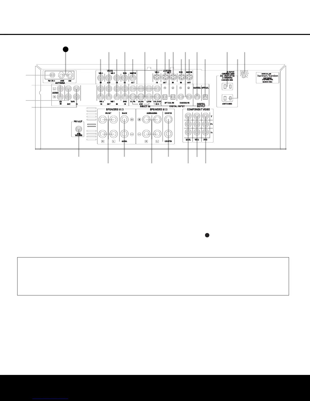
REAR-PANEL CONNECTIONS
¡ FM Antenna Jack
™ CD Audio Inputs
£ Tape Outputs
¢ Tape Inputs
∞ Subwoofer Output
§ Front Speaker Outputs
¶ Surround Back Speaker Outputs
• Surround Speaker Outputs
ª Center Speaker Outputs
‚ Component Video Monitor Outputs
⁄ Video 2 Component
Video Inputs
¤ DVD Component Video Inputs
‹ AC Power Cord
› Switched AC Accessory Outlet
fi Unswitched AC Accessory Outlet
fl Optical Digital Audio Output
‡ Coaxial Digital Audio Output
° S-Video Monitor Output
· Coaxial Digital Audio Inputs
a DVD S-Video Input
b Video 1 S-Video Input
c Optical Digital
Audio Inputs
d Video 1 S-Video Output
e Video 2 S-Video Input
f 6/8-Channel Direct Inputs
g Video Monitor Output
h DVD Audio/Video Inputs
i Video 1 Audio/Video Inputs
j Video 1 Audio/Video Outputs
k Video 2 Audio/Video Inputs
AM Antenna Terminals
33
34
35
36
37
38
39
40
41
4
8
49
4
6
47
4
4
45
4
2
43
38
39
40
41
31
32
30
28
29
25
26
27
28
29
30
24
23
22
21
20
31
37
36
35
34
33
32
31
37
36
35
34
33
32
48
49
50
51
47
46
45
44
43
42
NOTE: To assist in making the correct connections
for multichannel input, output and speaker connec-
tions
,
all connection jacks and ter
minals are color
-
coded in conformance with the CEA standards as
follows:
Front Left: White
Front Right: Red
Center: Green
Surround Left:
Blue
Surround Right: Gray
Surround Back Left: Brown
Surround Back Right: Tan
Subwoofer: Purple
Coaxial Digital Audio: Orange
Composite
Video:
Y
ellow
Component Video “Y”: Green
Component Video “Pr”: Red
Component Video “Pb”: Blue
¡ FM Antenna Jack: Connect the supplied indoor
(or an optional external) FM antenna to this terminal.
™ CD Audio Inputs: Connect these jacks to the
analog audio output of a compact disc player or CD
changer
.
£
Tape Outputs: Connect these jacks to the
RECORD/INPUT
jacks of an audio recorder.
¢ Tape Inputs:
Connect these jacks to the
PLAY/OUT
jacks of an audio recorder.
∞ Subwoofer Output: Connect this jack to the line-
level input of a powered subwoofer. If an external sub-
woofer amplifier is used, connect this jack to the sub-
woofer amplifier input.
§ F
ront Speaker Outputs:
Connect these outputs
to the matching + or – ter
minals on your left and right
speakers. When making speaker connections always
make certain to maintain correct polarity by connecting
the color
-coded (white for front left and red for front
right) (+) terminals on the AVR 135 to the red (+)
terminals on the speakers and the black (–) terminals
on the AVR 135 to the black (–) terminals on the
speakers
. See page 12 for more information on
speaker polarity.
¶ Surround Back Speaker Outputs: These
speaker ter
minals are nor
mally used to power the sur-
round back speaker in a 6.1-channel system. Connect
these outputs to the matching + and – terminals on
your surround back channel speaker
.
In confor
mance
with the CEA color
-code specification, the brown ter-
NOTE: To make it easier to follow the instructions that refer to this illustration, a larger copy may be downloaded from the Product Support section for this product
at www.harmankardon.com.
AVR 135 OM 12/3/04 12:11 PM Page 7

 Loading...