USE ONLY HAYWARD GENUINE REPLACEMENT PARTS 7
MODEL
NUMBER
EFFECTIVE
FILTRATION AREA
MAXIMUM
WORKING
PRESSURE
REQUIRED CLEARANCE MEDIA REQUIRED
SIDE ABOVE TYPE AMOUNT
FT
2
M
2
PSI B
R INCH MM INCH MM FILTER
SAND**
LBS KG
S200 2.2 .20 50 3.45 18 460 24 610 0.45-0.55mm 200 90
TABLE 1 **Also known as No. 20 Silica Sand.
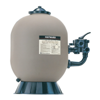
SPECIFICATIONS
PARTS
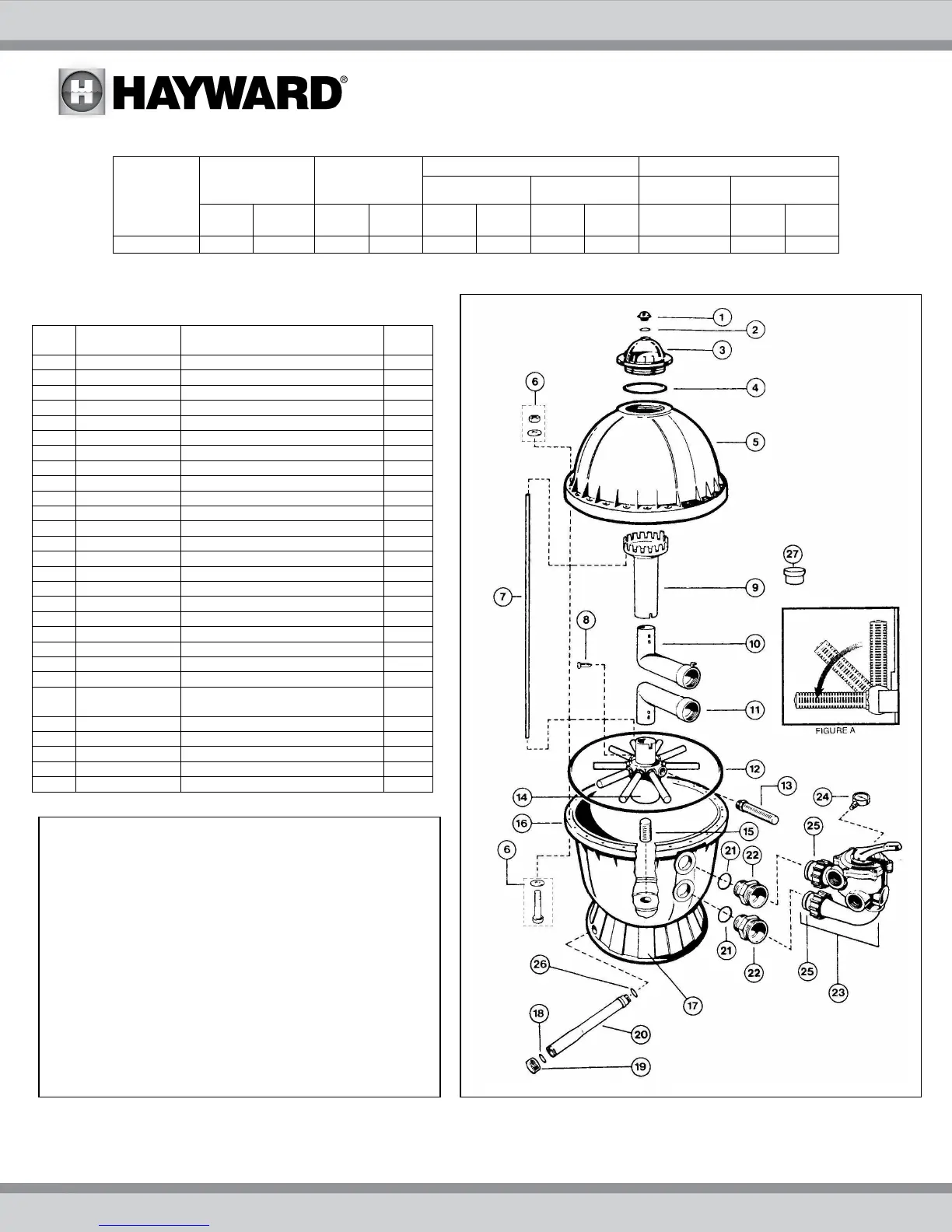
Model S200
REF
NO
PART
NO.
DESCRIPTION NO.
REQ
1 SX200G Manual Air Relief Cap 1
2 SX200Z5 O-ring, 13/16” O.D. 1
3 SX200K Access Dome 1
4 SX200Z6 O-Ring 1
5 SX200BT Filter Tank Head (Top) 1
6 ECX1642A
Head Bolt Kit, (Bolt, Nut, Washers)
10
7 SX200Z1 Plastic Air Tube 1
8 SX200Z2 Air Tube Lock Screw 1
9 SX200L Top Diffuser 1
10 SX200C Top Elbow Assembly 1
11 SX200C1 Bottom Elbow Assembly 1
12 SX200Z7 Body O-Ring 1
13 SX200QN Lateral (One Piece) 10
14 SX202QA Lateral Holder Assy w/S200QN 1
15 SX200H Bottom Screen 1
16 SX200AA1T Filter tank Bottom W/Drain Assy 1
17 SX200J Filter Support Stand (Skirt) 1
18 SX200Z9 Gasket 1
19 SX200Z8A Drain Cap Kit (with Gasket) 1
20 SX200EB Drain Pipe Assy W Cap& Gasket 1
21 SX200Z3 O-Ring 2
22 SX200D Bulkhead Fitting 2
23 SP0710X32 1 ½” Vari-Flo Control Valve
Assembly with Gauge
1
24 ECX27061 Pressure Gauge 1
25 SX200Z4 O-Ring 2
26 SX200Z14 O-Ring 1
27 SX200Z10 Cap Plug 1
S200PAK3 Pump/Filter Base (see Page 6)
The drain pipe assembly may be shipped loose to
prevent possible damage during field handling
and installation of the system.
The drain pipe assembly must be installed prior to
filling system.
To install drain pipe assembly:
1. Insert pipe, with o-ring, through the hole in the
base assembly.
2. Align and screw the pipe assembly into the
threaded hole in the bottom of the filter tank –
hand tight.
3. Apply wrench to “flats” next to the cap and
tighten approximately ¼ turn.
 Loading...