USE ONLY HAYWARD GENUINE REPLACEMENT PARTS 1
GENERAL
1. Proper fitting make-up is hand tight plus one to 1-
1/2 turns maximum. Always use Teflon pipe tape
or Permatex No.2 for connections to provide a
good, "living" seal.
IMPORTANT: Do not over tighten pipe fittings.
2. SERVICING VALVE: If it becomes necessary to
service or gain access to the key or valve seat
gasket:
a. Set handle in “Winterizing” position.
b. Remove cover screws.
c. Lift cover and key assembly out.
3. RE-ASSEMBLY VALVE:
a. Wipe debris from cover 0-ring.
b. Set handle in a “Winterizing” position. Align
flat edge on cover with body. Press down to
seat assembly.
c. Secure assembly to body with cover screws
and nuts. Tighten cover screws evenly and
alternately.
Do not over tighten.
FUNCTIONS OF VALVE POSITIONS
VALVE
SETTING
FLOW DIRECTION THROUGH VALVE
FILTER
(Sand Filter) PUMP - TOP - THROUGH FILTER - BOTTOM - RETURN
(DE Filter) PUMP - BOTTOM - THROUGH FILTER - TOP - RETURN
For normal filtration and vacuuming
ool through filter.
BACKWASH
Sand Filter) PUMP - BOTTOM - THROUGH FILTER - TOP – WASTE
(DE Filter) PUMP - BOTTOM - THROUGH FILTER - TOP - WASTE
For cleaning filter.
RINSE
PUMP - THROUGH FILTER in filter direction - WASTE
For initial start-up and clearing valve of debris after
backwashing.
WASTE
PUMP – THROUGH VALVE ONL
- WASTE
For vacuuming directly to waste, lowering pool level
and/or draining
ool.
CLOSED
NO CIRCULATION PAST PUMP POR
For shutting off all flow to filter and
ool.
RECIRCULATE
PUMP – THROUGH VALVE - RETURN
For b
assing filter, but circulating
ool water.
WINTERIZING:
Drain and winterize filter and pump per manufacturer's
instructions. To drain water from VariFlo® Multiport
valve—depress and rotate valve handle and place handle
ointer between an
detente
ositions.
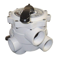
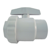
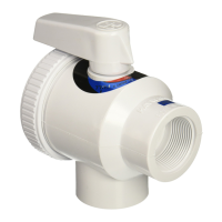
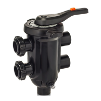
VariFlo
®
Multiport
2” Filter Control Valve
Owner’s Manual
Model: SP0715ALL
TURN OFF PUMP BEFORE CHANGING VALVE POSITION
CAUTION –Spring Hazard – Release of Valve spring compression can cause personal injury. To avoid, only remove handle
pin if servicing key O-ring. Remove handle pin before slowly removing Cover screws in an alternate pattern.
-
ea
an
o
ow a
nstruct
ons in this owner’s manual and on the equipment.
Failure to follow instructions can cause severe injury and/or death.
Hayward Pool Products
620 Division Street, Elizabeth, NJ 07207
Phone: (908) 355-7995
WWW.HAYWARD.COM
IS0715 REV B
REF
NO.
PART NUMBER DESCRIPTION
NO.
REQ’D
- SPX0710FL Handle, Large -
1SPX0715
Handle, Standard 1
2 SPX0710XZ7 Pin, for Handle 1
3 SPX0710Z16 Non-Metallic Bearin
1
SPX0715G Valve Position Label 1
4SPX0710Z1
Cover screw set with nuts (Set of 6) 1
5SPX0715Z1Cover O-rin
1
6SPX0603SSprin
1
7 SPX0710Z62 Spring Washer Set (Set of 2) 1
8SPX0735G
O-ring & TFE Shaft seal set 1
9SPX0710
¼” Plastic Pipe Plu
1
10 SPX0715D Valve Seat Gasket 1
11 SPX0715C Key 1
SPX0715B
Key, Cover & Handle Assembly 1