USE ONLY HAYWARD GENUINE REPLACEMENT PARTS
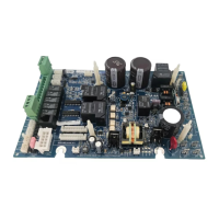
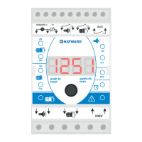
GLX-PCB-PRO
Main Printed Circuit Board (PCB) for Pro Logic
TM
This replacement assembly may support additional features than the board it replaces. For detailed information, download your model’s manual* from the
web at http://www.hayward-pool.com.
*P4 models: Pro Logic Installation manual (Oct 08 or later)
*P4 models: Pro Logic Operation manual (Oct 08 or later)
*PS models: Pro Logic Installation manual (Oct 08 or later)
*PS models: Pro Logic Operation manual (Oct 08 or later)
Compatibility
This circuit board is compatible with all Pro Logic “P-4”, “PS-4”, “PS-8” and “PS-16” units. The microprocessor software will automatically check the type of
local display that is connected and adjust the Pro Logic features and operation to match the appropriate model type.
If no local display is connected, or if there is a problem with the local display and it does not respond to inquiries from the main PCB, then the main PCB will
assume that the system is a Pro Logic P-4 model. If this occurs: First fix the problem (install or fix the local display) and then cycle power off and back on.
The Pro Logic will recheck the local display and operate accordingly.
Circuit Board Replacement
1. Record the System Settings: The Configuration, Timers, and Settings menus contain all of the information regarding how the Pro Logic is programmed
to operate a specific pool system. This information is stored on the main PCB and it is very important that all of this information gets transferred from
the old PCB to the new PCB. Record all programming information (Configuration menu, Timers menu, and Settings menu) before attempting to replace
the board.
2. Remove the old board: Make sure that ALL circuit breakers are OFF prior to PCB removal.
a. Remove metal panel to expose the local display and circuit board.
b. Remove the local display by pulling up and unplugging cable.
c. Unplug the sensor and display communication terminal blocks from the old PCB - you don’t need to disconnect/reconnect individual wires.
d. Remove transformer wires and any other wires that are connected to the old board, making note of their locations.
e. Remove the board by loosening the 2 mounting screws and sliding the board forward. When the board comes loose from the enclosure, pull it up
and out.
3. Install the new GLX-PCB-PRO circuit board:
a. Install the new board using the two mounting screws.
b. The locations of the transformer lugs may be different from the old board. Refer to the wiring diagram on the back page of this sheet for trans-
former wiring information.
c. Connect the remaining wires including the sensor and display communication terminal blocks onto the new circuit board. If there are any questions
about wiring locations, refer to the Installation manual found on the web.
d. Plug in and install the local display so that the new PCB can properly determine the system model type (P-4, PS-4, PS-8, PS-16).
4. Turn power on and reset Configuration to Default:
a. Turn power back on to the Pro Logic and confirm that the board is working properly.
b. Reset all of the Configuration parameters to their Default values using the following instructions:
c. Enter the prior programming information using the Configuration, Timers and Settings menus.
092364A RevB
Configurat ion
Menu-Unlocked
Configurat ion
Menu-Locked
Press repeatedly until “Configuration Menu” is displayed
Press left arrow button
Press BOTH buttons SIMULTANEOUSLY for 5 seconds to unlock
Reset Config. t o
Default Press +
Are you sure?
+ t o proceed
Config. reset
Confirmed
Initiate reset of all configuration parameters
Reset all configuration parameters
Move to previous/next configuration menu (config. not reset)
Move to previous/next menu (config. not reset)
Move to previous/next configuration menu