EasyManua.ls Logo

Heathkit AT-1 User Manual

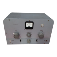
Heathkit AT-1
13 pages
To Next Page IconTo Next Page
To Previous Page IconTo Previous Page
Page #6 background image
Question and Answer IconNeed help?

Do you have a question about the Heathkit AT-1 and is the answer not in the manual?

Heathkit AT-1 Specifications

General IconGeneral
ModulationAM
ModesCW
Power SupplyExternal
Tube lineup6L6
Frequency Range80, 40, 20, 15, 10 meters

Summary

Introduction to Heathkit AT-1 Transmitter

Circuit Description of Heathkit AT-1 Transmitter

Heathkit AT-1 Operation Adjustments

80 Meter Operation Adjustments

Instructions for tuning the transmitter on the 80 meter band, including power and standby switch settings.

40 Meter Operation Adjustments

Procedure for tuning the transmitter on the 40 meter band, including meter and driver controls.

20, 15, 11 and 10 Meter Operation Adjustments

Method for tuning the transmitter on 20, 15, 11, and 10 meter bands using crystal frequencies.

Radio Telephone Operation for Heathkit AT-1

Modulator Design for Heathkit AT-1

Formula and example for calculating the load impedance presented by the radio frequency amplifier for modulation.

Modulation Connections to the AT-1

VFO Operation with Heathkit AT-1

Troubleshooting Heathkit AT-1 Transmitter Issues

Television Interference (TVI) Elimination

Replacements and Service Information

Component Replacements for Heathkit AT-1

Information on how to identify and order replacement parts for the AT-1 transmitter.

Heathkit AT-1 Service and Repair

Details on returning the instrument for inspection and repair by the Heath Company.

Heathkit AT-1 Parts List

Related product manuals