17
10
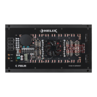
Level controls
These controls are used to adapt the input sensitivi-
ty of the individual channels to the output voltage of
the connected signal source.
This is not a volume control, it´s only for adjusting
the amplier gain. The control range is 1 - 8 Volts.
The setting of the controls also aects the digital
signal inputs of the optionally available HDM 2 mod-
ule if the SPDIF Direct In switch is not set to “On”
position.
11
Stereo / Bridged switch
These switches are used to set the operating mode
of the amplier.
4-channel operation: If the amplier operates in
4-channel mode both switches have to be set to
STEREO.
3-channel operation: If the amplier operates in
3-channel mode (front system + subwoofer) set
the switch of the channel pair A / B (front system)
to STEREO and the switch of the channel pair C / D
to BRIDGED.
For the bridged channel, both inputs (C and D) must
be assigned, since both channels form a sum sig-
nal. If there is only a mono signal for the subwoofer,
the signal must be distributed to both inputs using
a Y-adapter.
2-channel operation: If the amplier operates in
2-channel mode both switches have to be set to
BRIDGED.
In this mode the input channels A and B as well as
C and D each generate a summation signal (mono
signal).
12
Input Mode switch (2-CH / 4-CH)
This switch is used to route the input signals to the
respective amplier channels.
4-channel mode (4-CH): If the head unit / car radio
provides two stereo outputs (front left / right, rear
left / right), all four signal inputs of the amplier are
supplied with the corresponding output signals of
the head unit / car radio.
2-channel mode (2-CH): If the head unit / car radio
only provides one stereo output (left / right), all am-
plier channels are supplied with this signal. This
means, that only the inputs of the channels A and B
need to be connected. In this mode the input signal
of channel A is routed to channel C and channel B
is routed to channel D.
Please consider that the fader and balance control
of the head unit have the same eect on channels A
and C and respectively B and D.
13
Power & Protect LED
The power and protect LED indicates the operating
mode of the amplier.
Green: The amplier is ready for operation.
Yellow: The amplier is overheated. The internal
temperature protection shuts down the device until
it reaches a safe temperature level again.
Flashing yellow: The fuses inside the device are
blown. Please check the fuses and, if necessary,
replace them. They may only be replaced by identi-
cally rated fuses (3 x 30 Ampere) to avoid damage
of the amplier.
Red: A malfunction has occurred that may have dif-
ferent root causes. The HELIX C FOUR is equipped
with protection circuits against over- and undervolt-
age, short-circuit on loudspeakers and reverse con-
nection. Please check for connecting failures such
as short-circuits or other wrong connections. If the
amplier does not turn on after that it is defective
and has to be sent to your local authorized dealer
for repair service.
14
Fuses
The input fuses are connected in parallel and pro-
vide protection against an internal fault of the de-
vice, therefore the system must be additionally pro-
tected by a further main fuse located close to the
battery (max. distance from battery: 30 cm / 12”).
The HELIX C FOUR is equipped with 3 x 30 Am-
pere fuses.
 Loading...