Installation Guide
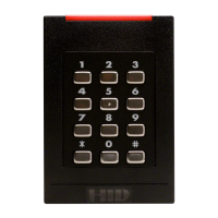
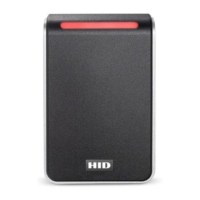
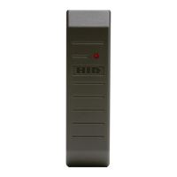
iCLASS Reader Models RK40 & RWK400
An ASSA ABLOY Group company ASSA ABLOY
_____________________________________________________________________________________________________
HID Corporation 9292 Jeronimo Road Irvine, CA 92618-1905 USA TEL (949) 598-1600 (800) 237-7769 FAX (949) 598-1690
Web page - www.hidcorp.com e-mail – tech@hidcorp.com iClass Keypad Reader Install Manual 6094-901 Rev A Page 1 of 2
PARTS INCLUDED SPECIFICATIONS
• 1 - iCLASS Keypad Reader • Voltage Range:
12VDC (10 - 16VDC).
• 1 - Installation Manual • Current:
100mA avg / 220mA peak.
• 2 - 3.5mm x .6 pitch x 12mm Phillips machine screws • Cable distance to Host:
500ft (152m) max – Wiegand.
• 3 - #6-32 x .375” Phillips self-tapping machine screws
50ft (15m) max – RS-232.
• 2 - #6 x 1.5” Phillips sheet metal screws
4000ft (1216m) max – RS-485.
• 1 - #6-32 x .375” Spanner security screw • Op. Temperature:
-31°F - +149°F (-35°C – +65°C)
Recommended:
• Open collector output:
Sink – 40mA, source – 1mA.
• Up to 10 wire splices *
Standards:
• Cable, 9 conductor, 22AWG, shielded (Wiegand)
• Cable , 6 conductor, 22AWG, shielded (Serial)
• Read/Write* capability in ISO 1SO 15693-2 mode with HID
iCLASS credentials.
• Linear DC Power Supply
• Metal or plastic junction box
• Security Tool (for security screw) HID 04-0001-03
• Read/Write* capability in ISO 1SO 14443-B mode with HID
iCLASS 16KS.
• Magnetic Tamper switch - Ademco 945T, Sentrol
1038T, GRI 100T or 110T or Aleph DC-2531
• Read capability of CSN/UID in ISO 1SO 14443-A1 mode
with HID Mifare and other 3
rd
party Mifare credentials.
* RK40 available with 18” wire pigtail or 10-pos. removable
screw terminal connector. RWK400 includes 8-pos. and 10-
pos. removable screw terminal connectors.
* RK40 is a read only, while RWK400 is a read/write unit.
INSTALLATION
1- Disassemble
A. Remove the screw at the bottom of the unit.
B. Lift the mounting plate out at the bottom side
C. Slide mounting plate down
2- Install Tamper Switch
An internal magnet provides tamper indication when used with a magnetic reed switch connected to an external alarm
system. Locate Switch behind the left side of the mounting plate, centered between the mounting holes.
Electrical Back Box Wall Surface