MaxiProx
®
Installation Guide Part No. 5375-901, Rev E.1
March 2012 Page 15 of 19
© 2008-2012 HID Global Corporation. All rights reserved.
4.1.2 Output Specification
The specifications of voltage, current, power and timing are from the perspective of the reader. A
common signal ground is defined as a voltage reference that is common to both the reader and the
control panel. The voltages for the data outputs are referenced from the power supply ground located
at the reader. The voltage measured for the power to the reader is referenced from the power supply-
return connection location at the reader, not at the source of the power.
The voltage, current, and timing of the data pulses are measured at the reader in reference to the
power supply/signal ground at the reader. The voltage, current and timing of a signal driving an
auxiliary input device on a reader is measured at the control panel that is controlling the input device
(with reference to the signal ground at the panel).
4.1.3 Signal Levels
The Data One, Data Zero, and LED Control conductors connect signals between the reader and the
panel. The logic levels are defined as follows:
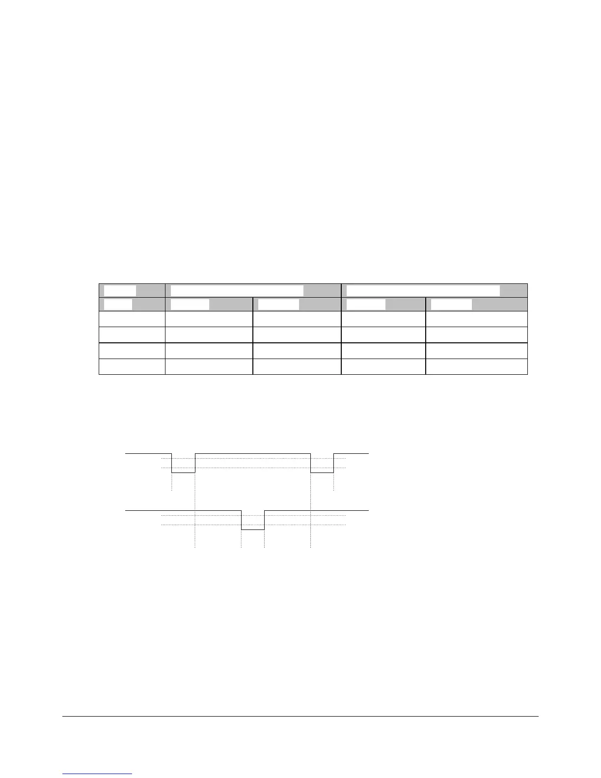
Table 9: Logic Levels
Data Outputs (Data0 and Data1)
Control Inputs (LED’s, Hold, Beeper)
Voh 3.5V 5.5V 3.5V 5.5V
Vol 0.0V 0.5V 0.0V 0.5V
Ioh 0.0mA 5.0mA -1.0mA 0.0mA
Iol -25.0mA 0.0mA 0.0mA 25.0mA
4.1.4 Data Pulses
The Data One and Data Zero signals are normally held at a logic high level until the reader is ready to
send a data stream. The reader places asynchronous low pulses on the appropriate data lines to
transmit the data stream to the panel. The following timing parameters shall be observed:
Data One
Data Zero
Tpw Tpw
Tpw TpiTpi
Voh
Voh
Vol
Vol
Table 10: Data Pulses - Timing Parameters
• Tpw Pulse Width Time - 30uS (minimum) to 50uS (maximum)
• Tpi Pulse Interval Time - 1.8mS (minimum) to 2.2mS (maximum)
 Loading...