- 10 -
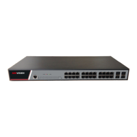
Figure 3-3 RJ-45 connector of the console port
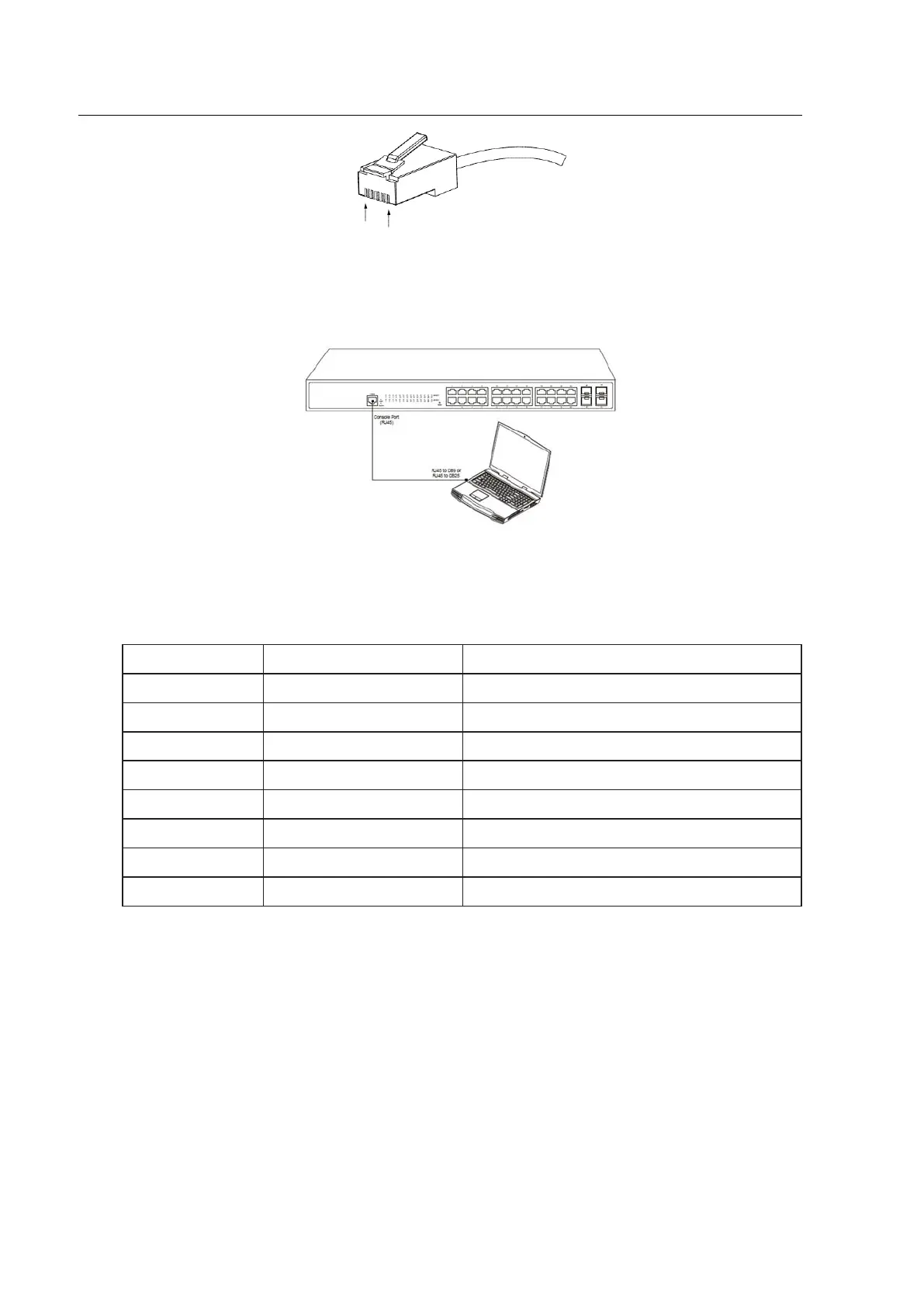
Figure 3-4: Connecting the console port of 24 SWITCH with the computer
Table 3-1 Definition of the pins of the Console port
Note: The console port of the 24 SWITCH does not support traffic control. Therefore, you
must set the option data traffic control to none when you configure the switch with the super
terminal. Otherwise, the single-pass problem will arise on the super terminal.
The cable is used to connect the console port of the 24 SWITCH and the outside console
terminal device. One end of the console port is RJ45 8-core plug and the other end of the
console port is a 25-hole plug and a 9-hole plug. The RJ45 plug is put into the socket of the
console port on the 24 SWITCH switch. DB25 and DB9 is alternative. RJ45 connects to DB9
in the console port shown as below.
 Loading...