Chapter 3 Installaon
3.1 DIP Switch Descripon
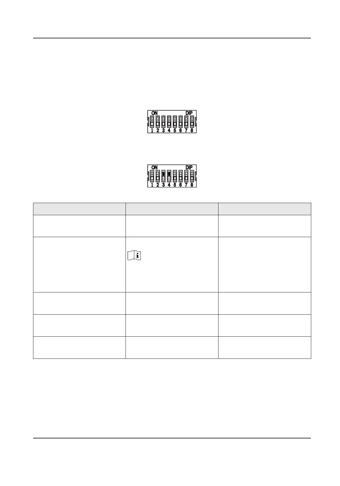
The DIP switch module is shown below. The No. of DIP switch from le to right is 1 to 8.
When the switch is towards ON, it means the switch is enabled, otherwise, the switch is o. If you
set the DIP switch like the gure displayed below, its binary value is 00001100, and its decimal
value is 12.
Table 3-1 Descripon of DIP Switch
No. Descripon DIP Switch Status
1 to 4 Address of RS-485 1: 1
0: 0
5 Card Security
Note
• For DS-K1108AE/AEK, the
DIP switch is reserved.
1: Enable M1 card encrypon
funcon, and disable door
open via NFC card.
0: Disable M1 card
encrypon
funcon,
enable door open via
NFC card, and read card No.
6 Wiegand protocol or RS-485
protocol.
1: Wiegand protocol
0: RS-485 protocol
7 Wiegand Protocol (available
when No. 6 is 1)
1: Wiegand protocol of 26-bit;
0: Wiegand protocol of 34-bit.
8 Matched Resistance (available
for RS-485 protocol)
1: Enable
0: Disable
3.2 Wiring Cables
Wire the cables between controller and card reader, thus to establish the communicaon between
them.
DS-K1108A Series Card Reader User Manual
4
 Loading...