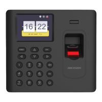
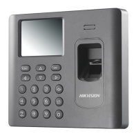
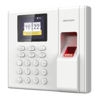
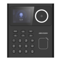
Appearance
1
Installation
2
©2020 Hangzhou Hikvision Digital Technology Co., Ltd.
It includes instrucons on how to use the Product. The soware embodied in the Product is
governed by the user license agreement covering that Product.
About this Manual
This Manual is subject to domesc and internaonal copyright protecon. Hangzhou Hikvision
Digital Technology Co., Ltd. (“Hikvision”) reserves all rights to this manual. This manual cannot be
reproduced, changed, translated, or distributed, parally or wholly, by any means, without the
prior wrien permission of Hikvision.
Trademarks
and other Hikvision marks are the property of Hikvision and are registered
trademarks or the subject of applicaons for the same by Hikvision and/or its affiliates. Other
trademarks menoned in this manual are the properes of their respecve owners. No right of
license is given to use such trademarks without express permission.
Legal Disclaimer
TO THE MAXIMUM EXTENT PERMITTED BY APPLICABLE LAW, THE PRODUCT DESCRIBED, WITH ITS
HARDWARE, SOFTWARE AND FIRMWARE, IS PROVIDED “AS IS”, WITH ALL FAULTS AND ERRORS,
AND HIKVISION MAKES NO WARRANTIES, EXPRESS OR IMPLIED, INCLUDING WITHOUT
LIMITATION, MERCHANTABILITY, SATISFACTORY QUALITY, FITNESS FOR A PARTICULAR PURPOSE,
AND NON-INFRINGEMENT OF THIRD PARTY. IN NO EVENT WILL HIKVISION, ITS DIRECTORS,
OFFICERS, EMPLOYEES, OR AGENTS BE LIABLE TO YOU FOR ANY SPECIAL, CONSEQUENTIAL,
INCIDENTAL, OR INDIRECT DAMAGES, INCLUDING, AMONG OTHERS, DAMAGES FOR LOSS OF
BUSINESS PROFITS, BUSINESS INTERRUPTION, OR LOSS OF DATA OR DOCUMENTATION, IN
CONNECTION WITH THE USE OF THIS PRODUCT, EVEN IF HIKVISION HAS BEEN ADVISED OF THE
POSSIBILITY OF SUCH DAMAGES.
REGARDING TO THE PRODUCT WITH INTERNET ACCESS, THE USE OF PRODUCT SHALL BE WHOLLY
AT YOUR OWN RISKS. HIKVISION SHALL NOT TAKE ANY RESPONSIBILITIES FOR ABNORMAL
OPERATION, PRIVACY LEAKAGE OR OTHER DAMAGES RESULTING FROM CYBER ATTACK, HACKER
ATTACK, VIRUS INSPECTION, OR OTHER INTERNET SECURITY RISKS; HOWEVER, HIKVISION WILL
PROVIDE TIMELY TECHNICAL SUPPORT IF REQUIRED.
SURVEILLANCE LAWS VARY BY JURISDICTION. PLEASE CHECK ALL RELEVANT LAWS IN YOUR
JURISDICTION BEFORE USING THIS PRODUCT IN ORDER TO ENSURE THAT YOUR USE CONFORMS
THE APPLICABLE LAW. HIKVISION SHALL NOT BE LIABLE IN THE EVENT THAT THIS PRODUCT IS
USED WITH ILLEGITIMATE PURPOSES.
IN THE EVENT OF ANY CONFLICTS BETWEEN THIS MANUAL AND THE APPLICABLE LAW, THE LATER
PREVAILS.
Data Protecon
During the use of device, personal data will be collected, stored and processed. To protect data,
the development of Hikvision devices incorporates privacy by design principles. For example, for
device with facial recognion features, biometrics data is stored in your device with encrypon
method; for fingerprint device, only fingerprint template will be saved, which is impossible to
reconstruct a fingerprint image.
As data controller, you are advised to collect, store, process and transfer data in accordance with
the applicable data protecon laws and regulaons, including without limitaon, conducng
security controls to safeguard personal data, such as, implemenng reasonable administrave and
physical security controls, conduct periodic reviews and assessments of the effecveness of your
security controls.
DS-K1A802A Series
Fingerprint Time Aendance Terminal
Quick Start Guide
UD15388B-B
Screen
Keypad Card Presenng Area USB Interface Debugging
Port
Power
Interface
Network
Interface
Fingerprint
Recognion Area
Keypad Descripons
ESC OK
1
2
ABC
3
DEF
4
GHI
6
MNO
7
PQRS
8
TUV
9
WXYZ
5
JKL
Exing Key
Direcon
Keys
Numeric Keys/
Leer Keys
OK Key
Eding Key
Deleng
Key
0
OK Key: Press the key and confirm operaons. Hold the key
for 2 s to enter the login interface.
Deleting Key: Press the key to delete the entered leer or
number.
If the device supports connecng lithium baery, long press
the key to power off the device.
Numeric Keys/Letter Keys: Press the key to enter numbers
or leers.
Key 0 can also represent a space key except you are using the
number input method.
Exiting Key: Press the key to exit the menu.
Direction Keys: Press , , and to move the cursor
on the screen. Or on the text entering page, press up or down
buon to change the input method.
Editing Key: Press the key to enter the eding status.
You can shi among numbers/lowercases, numbers/uppercases
and symbols.
Notes:
1. The pictures here are for reference only. Some models do not support
card presenng funcon. For details, refer to the actual products.
2. If the aendance mode is Manual, the OK key, the direcon
key, and the exing key can be the shortcut key of the aendance status.
140 mm
155 mm
28 mm
Front View Side View Back View Keypad
Method 1:
Wall Mounting
without
Mounting Plate
Method 2:
Wall Mounting
with
Mounting Plate
2. Insert the screw sockets of the setscrews in the drilled
holes.
3. Fix and fasten the screws in the sockets on the wall or
other places. (You should reserve 5.2 mm to 5.5 mm for
the hanging the device when fix and fasten the screws.)
4. Align the 4 holes on the device plate with
the fixed screws and hang the device on the
wall.
1. Drill 4 holes on the wall or other places
according to the mounng template. (Supplied)
Note: The length and width will be 2 to 3 mm
smaller than the actual device’s.
152 mm
127 mm
Steps:
1. Install the gang box on the wall.
Note:
•
Make sure the gang box screw holes match the mounng plate’s.
•
The gang box here is for reference only. Select an appropriate gang box to
install.
•
The gang box is not supplied.
2. Fix the mounng plate on the gang box with 2 supplied screws
(SC-PM4X10-IMP).
3. Route the device cable through the cable hole of the mounng plate and
insert the cables in the gang box.
4. Align the terminal with the mounng plate, and secure the terminal on
the mounng plate with two supplied socket hexagon screws
(SC-KM3X10_3-SUS).
4
4
Device
Mounting
Plate
Gang
Box Wall
1
2
3
120 mm
130.6 mm
25.15 mm
66.6 mm
53.2 mm
36.5 mm
83.65 mm
68.1 mm