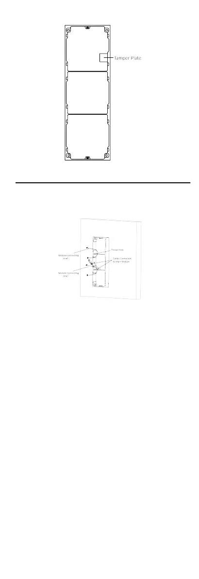
Figure 4-19 Mounng Frame
5. Thread the module-connecng line across the thread holes of
the frame. Pass the main unit connecng line across the thread
hole to the top grid.
Figure 4-20 Placement of Lines
6. Connect the cables.
1) Connect the lines and module-connecng line 1 to the
corresponding interfaces of the main unit, then place the
main unit into the upper grid.
2) Connect the other end of the
module-connecng line 1 to
the input interface of the sub module. Connect two sub
modules via
module-connecng line 2.
3) Organize the cables with cable e in the package. The
suggested cable connecon picture as shown below.
21
 Loading...