2) Connect the other end of the module-connecng line 1 to
the input interface of the sub module. Connect all sub
modules via module-connecng lines.
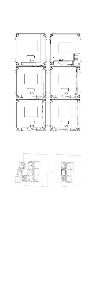
3) Organize the cable with cable e in the package. The
suggested cable
connecon picture as shown below.
Figure 4-36 Line Connecon Eect Picture
9. Insert the modules into the frame aer wiring. The main unit
must be placed in the top grid on the le.
Figure 4-37 Insert the Modules
10. Pull the grounding line out and xed its two end to the screw
on the cover.
28
 Loading...