3
1
3 4
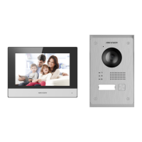
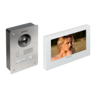
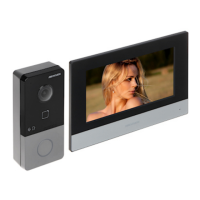
DS-KIS703-P
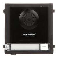
DS-KV8103-IMPE2
Video Intercom Villa Door Staon
Video Intercom Two-Wire Bundle
E N G L I S H
UD17634B-A
2
1
2
3
4
5
6
7
8
9
40
Unit:mm
103
162
120
83
Screws Door Station Door Station
Screws Junction Box Wall
2
3
1
Screws
Screws Gang Box Wall
3
2
1
Appearance
Installaon
Before you begin:
Surface Mounng with Gang Box
1
3
Geng Started
4
Video Intercom Operaon
5
Terminals
2
Microphone
Calling Indicator
Speaking Indicator
1 2 3
4 5 6
7
1. Make sure the device in the package is in good condion and all the assembly parts
are included.
2. Make sure all the related equipment is power-off during the installaon.
3. Check the product specificaon for the installaon environment.
4. Connect cables to the door staon before mounng.
1. Take the gang box and screws from the packing box.
2. Fix the gang box onto the wall with 4 screws.
3. Install the door staon into the gang box, and fix it with 4 screws.
Supplement Light
Built-in Camera
Open Door Indicator
Loudspeaker
8
TAMPER 9 Call Buon
To install the door staon onto the wall, you are required to ulize a matched gang box.
The dimension of gang box is shown.
The door staon supports surface mounng and flush mounng.
Refers to Video Intercom Villa Door Staon User Manual(scan the QR code) for details.
1. Press the call buon of the door staon.
2. The resident can receive/decline the video call, unlock the door, etc.
Note:
When the video intercom between you and the resident is realized, you can speak to the
resident, and the live view of door staon will be displayed on the connected indoor
staon.
When the door staon is calling the resident, the door staon will detect the brightness
of video automacally. When the brightness is lower than the expected threshold, the
supplement light will be enabled.
When the supplement light is enabled, the backlight of key will be auto-enabled,
otherwise, the door staon will detect the brightness of live view and enable the backlight
of key when the brightness of live view is lower than expected threshold.
You can call the resident by pressing the call buon.
Flush Mounng with Gang Box
1. Cave the installaon hole, and pull the cable out.
Note: The suggested dimension of the installaon hole is 103.5 mm × 162.5 mm × 40.5
mm.
2. Insert the gang box into the hole with 4 screws.
3. Install the door staon into the gang box, and fix it with 4 screws.
Wire the door staon to the indoor staon with 2-wire cables.
You can acvate the door staon by indoor staon.
Set the open duraon and other parameters by indoor staon.
Refers to the Indoor Staon Configuraon Guide for details.
The applicaon of the device is shown.
A1
A2
A3
A4
A5
A6
NC1 : Normally Close
NO1 : Normally Open
COM : Common Interface
GND : Grounding
NC2 : Normally Close
NO2 : Normally Open
A7
A8
A9
A
10
A11
AIN1 : Alarm Input 1
AIN2 : Alarm Input 2
12V OUT : Power Output for Lock
GND : Grounding
2-WIRE: Wire to Indoor Staon
NC1 NO1 NC2 NO2 GND GNDCOM
LOCK1
A1 A11
AIN2 AIN1
12V
OUT
2-WIRE
LOCK2 ALARM IN
LOCK POWER
Power Supply
Indoor StationDoor Station
Internet
Wi-Fi
2-wire cable
Multicore cable
Door Lock
Power Supply
APP Control
This product and - if applicable - the supplied accessories too are marked with "CE" and
comply therefore with the applicable harmonized European standards listed under the RE
Direcve 2014/53/EU, the EMC Direcve 2014/30/EU, the RoHS Direcve 2011/65/EU.
2012/19/EU (WEEE direcve): Products marked with this symbol cannot be disposed of as
unsorted municipal waste in the European Union. For proper recycling, return this product to
your local supplier upon the purchase of equivalent new equipment, or dispose of it at
designated collecon points. For more informaon see: www.recyclethis.info
2006/66/EC (baery direcve): This product contains a baery that cannot be disposed of as
unsorted municipal waste in the European Union. See the product documentaon for
specific baery informaon. The baery is marked with this symbol, which may include
leering to indicate cadmium (Cd), lead (Pb), or mercury (Hg). For proper recycling, return
the baery to your supplier or to a designated collecon point. For more informaon see:
www.recyclethis.info
FCC Conditions
This device complies with part 15 of the FCC Rules. Operaon is subject to the following two condions:
1. This device may not cause harmful interference.
2. This device must accept any interference received, including interference that may cause undesired
operaon.
EU Conformity Statement
FCC Information
Please take aenon that changes or modificaon not expressly approved by the party responsible for
compliance could void the user’s authority to operate the equipment.
FCC compliance: This equipment has been tested and found to comply with the limits for a Class B digital
device, pursuant to part 15 of the FCC Rules. These limits are designed to provide reasonable protecon against
harmful interference in a residenal installaon. This equipment generates, uses and can radiate radio
frequency energy and, if not installed and used in accordance with the instrucons, may cause harmful
interference to radio communicaons. However, there is no guarantee that interference will not occur in a
parcular installaon. If this equipment does cause harmful interference to radio or television recepon, which
can be determined by turning the equipment off and on, the user is encouraged to try to correct the
interference by one or more of the following measures:
—Reorient or relocate the receiving antenna.
—Increase the separaon between the equipment and receiver.
—Connect the equipment into an outlet on a circuit different from that to which the receiver is connected.
—Consult the dealer or an experienced radio/TV technician for help.
This equipment should be installed and operated with a minimum distance 20cm between the radiator and
your body.
Please take aenon that changes or modificaon not expressly approved by the party responsible for
compliance could void the user’s authority to operate the equipment.
This device complies with Part 15 of the FCC Rules. Operaon is subject to the following two condions:
(1) This device may not cause harmful interference, and
(2) This device must accept any interference received, including interference that may cause undesired
operaon.
This equipment complies with FCC radiaon exposure limits set forth for an uncontrolled environment. This
equipment should be installed and operated with minimum distance 20cm between the radiator & your body.