5
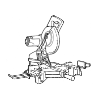
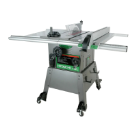
Fig. 2
Handle
Lock lever (C) (For Australia)
Motor
Head
Gear Case
Dust Bag
Laser Marker (Only C10FCH2)
Turn Plate
6 mm Wing Bolt
Vise Assembly
Sub Fence (B)
Fence (B)
Turntable
Side Handle
Lever
Indicator (A) (For miter scale)
Table Insert
Fence (A)
Indicator (B) (For bevel scale)
Lower Guard
Saw Blade
Motor
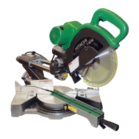
(2) During bevel and compound cutting, attach the dust bag
at a right angle to the base surface as shown in Fig. 3.
Fig. 3
CAUTION
䡬 Empty the dust bag frequently to prevent the duct and
the lower guard from becoming clogged.
Sawdust will accumulate more quickly than normal
during bevel cutting.
6. Installation
Ensure that the machine is always fixed to bench.
Attach the power tool to a level, horizontal work bench.
Select 8 mm diameter bolts suitable in length for the
thickness of the work bench.
Bolt length should be at least 35 mm plus the thickness
of the work bench.
For example, use 8 mm × 60 mm bolts for a 25 mm
thick work bench.
ADJUSTING THE POWER TOOL PRIOR TO USE
CAUTION
Make all necessary adjustments before inserting the
plug in the power source.
1. Check to see that the lower guard operates smoothly
CAUTION (For Australia)
䡬 This compound miter saw is equipped with a saw
head lock as safety device.
䡬 To lower the saw head to cut, the lock must be released
by pressing the lock lever (C) with your thumb.
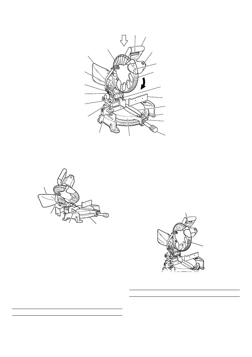
(1) When you push down the handle while pushing the
lock lever (C), check that the lower guard revolves
smoothly (Fig.4).
(2) Next, check that the lower guard returns to the original
position when the handle is raised.
PRACTICAL APPLICATIONS
WARNING
䡬 To avoid personal injury, never remove or place a
workpiece on the table while the tool is being operated.
䡬 Never place your limbs inside of the line next to
warning sign while the tool is being operated. This
may cause hazardous conditions (see Fig. 5).
Dust bag
Duct
Right angle
Base
Lock lever (C) (For Australia)
Lower Guard
Fig. 4
 Loading...