9
CAUTION
䡬 For maximum dimensions for cutting, refer to
“SPECIFICATIONS” table.
䡬 Increased pressure on the handle will not increase the
cutting speed. On the contrary, too much pressure
may result in overload of the motor and/or decreased
cutting efficiency.
䡬 Confirm that the trigger switch is turned OFF and the
power plug has been removed from the receptacle
whenever the tool is not in use.
䡬 Always turn the power off and let the saw blade stop
completely before raising the handle from the
workpiece. If the handle is raised while the saw blade
is still rotating, the cut-off piece may become jammed
against the saw blade causing fragments to scatter
about dangerously.
䡬 Every time one cutting of deep-cutting operation is
finished, turn the switch off, and check that the saw
blade has stopped. Then raise the handle, and return
it to the full retract position.
䡬 Be absolutely sure to remove the cut material from
the top of the turntable, and then proceed to the next
step.
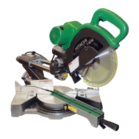
10. Miter cutting procedures
(1) Loosen the side handle and push the lever for angle
stoppers. Then, adjust the turntable until the indicator
aligns with desired setting on the miter scale (Fig. 16).
(2) Re-tighten the side handle to secure the turntable in
the desired position.
Fig. 16
NOTE
䡬 Positive stops are provided at the right and left of the
0° center setting, at 15°, 22.5°, 31.6° and 45° settings.
Check that the miter scale and the tip of the indicator
are properly aligned.
䡬 Operation of the saw with the miter scale and indicator
out of alignment, or with the side handle not properly
tightened, will result in poor cutting precision.
CAUTION
䡬 Never remove the side handle; use of the tool without
it would be hazardous.
To prevent an accident or personal injury always firmly
tighten the miter handle.
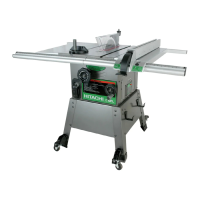
11. Bevel cutting procedures (Fig. 17)
(1) Loosen the clamp lever and bevel the saw blade to
the left.
(2) Adjust the bevel angle to the desired setting while
watching the bevel angle scale and indicator, then
secure the clamp lever.
Miter scale
Indicator
(For miter scale)
Side handle
Tighten
Loosen
Lever
Turntable
Turn the turntable
Push
Fig. 17
WARNING
䡬 When the workpiece is secured on the left or right
side of the blade, the short cut-off portion will come
to rest on the right or left side of the saw blade. Always
turn the power off and let the saw blade stop
completely before raising the handle from the
workpiece.
If the handle is raised while the saw blade is still
rotating, the cut-off piece may become jammed
against the saw blade causing fragments to scatter
about dangerously.
䡬 When stopping the bevel cutting operation halfway,
start cutting after pulling back the motor head to the
initial position.
Starting from halfway, without pulling back, causes
the safety cover to be caught in the cutting groove of
the workpiece and to contact the saw blade.
12. Compound cutting procedures
Compound cutting can be performed by following the
instructions in 9 and 10 above. For maximum
dimensions for compound cutting, refer to
“SPECIFICATIONS” table.
CAUTION
䡬 Always secure the workpiece with the right hand side
for compound cutting. Never rotate the table to the
right for compound cutting, because the saw blade
might then contact the clamp or vise that secures the
workpiece, and cause personal injury or damage.
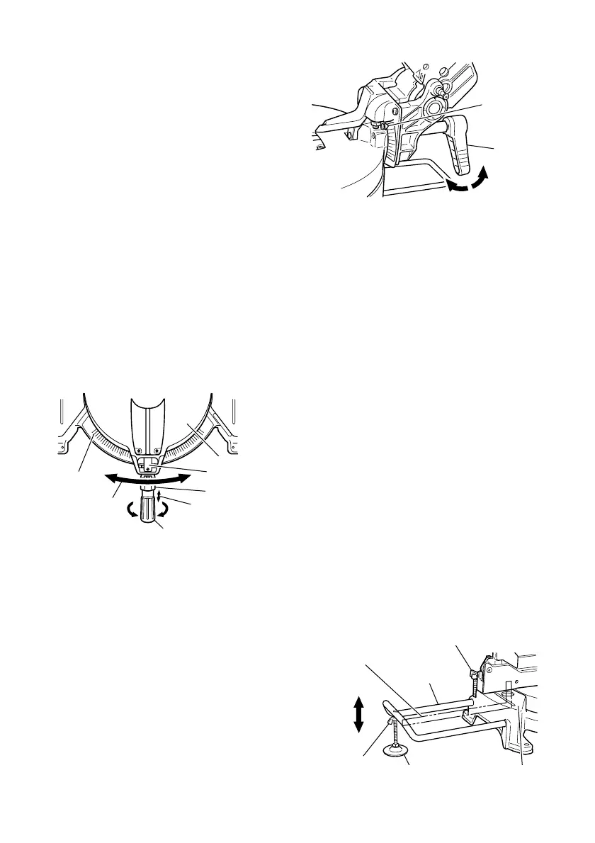
13. Installing the holders (Optional accessory)
The holders help keep longer workpieces stable and
in place during the cutting operation.
(1) As indicated in Fig. 18, use a steel square for aligning
the upper edge of the holders with the base surface.
Loosen the 6 mm wing nut. Turn a height adjustment
bolt 6 mm, and adjust the height of the holder.
Fig. 18
Loosen
Clamp lever
Tighten
Indicator
(for bevel scale)
6mm Wing bolt (Optional accessory)
Holder
(Optional
accessory)
Steel
square
Base
surface
6mm Wing
nut (Optional
accessory)
Height adjustment bolt 6mm
(Optional accessory)
 Loading...