--- 11 ---
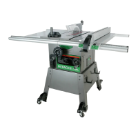
Ink line
Saw blade
Fig. 7
WARNING:
Before plugging the power plug into the receptacle, make sure that the main body and the laser
marker are turned off.
Exercise utmost caution in handling the switch trigger for the position adjustment of the laser line,
as the power plug is plugged into the receptacle during operation. If the switch trigger is pulled
inadvertently, the saw blade can rotate and result in unexpected accidents.
Do not remove the laser marker to use for other purposes.
Workpiece
Cutting width
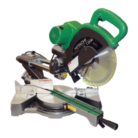
Move
4 mm hex.
bar wrench
Fig. 8
Laser line
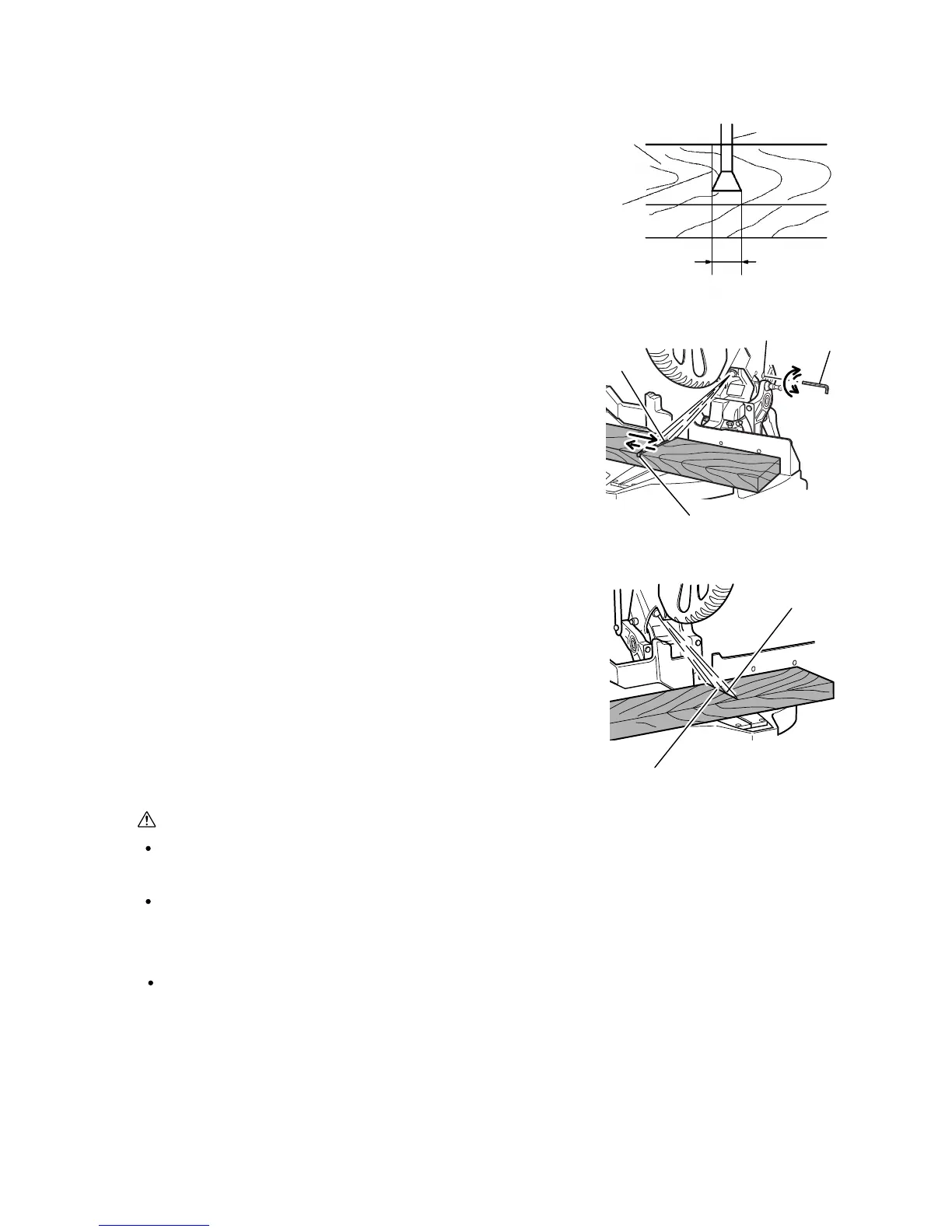
Turn
Ink line
Laser line
Fig. 9
Groove
8. ADJUSTMENT AND OPERATION PRECAUTIONS
8-1. Position Adjustment of Laser Line (Only the Model C 10FCH2)
The laser line is adjusted to the width of the saw blade at the time
of factory shipment. Depending upon the cutting choice, align the
laser line with the left side of the cutting width (saw blade) or the
right side according to the following procedure. First, make a right-
angle ink line on the workpiece that is about 38 mm (1-1/2") in
height and 89 mm (3-1/2") in width. To cut the right side of the ink
line with the saw blade as shown in Fig. 7, align the left side of the
saw blade with the ink line on the workpiece and make a groove of
about 5 mm deep on the workpiece to the middle. Hold the
grooved workpiece by the vise as it is and do not move it.
Light up the laser marker. Then insert a 4 mm hex. bar wrench in
the 12 diameter hole on the side of the gear case, turn the hex.
socket set screw to move the laser line. (If you turn the hex. socket
screw clockwise, the laser line will shift to the right and if you turn it
counterclockwise, the laser line will shift to the left.) (Fig. 8)
Thus the cutting position matches the laser line position. Align the
ink line on the workpiece with the laser line. When aligning the ink
line, slide the workpiece little by little and secure it by vise at a
position where the laser line overlaps with the ink line (Fig. 9).
Work on grooving again and check the position of the laser line.
When the ink line and the laser line are overlapped, the strength
and weakness of light will change, resulting in a stable cutting
operation because you can easily discern the conformity of lines.
This ensures the minimum cutting errors.
 Loading...