4
English
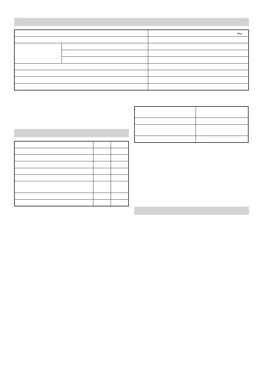
SPECIFICATIONS
Voltage (by areas)* (110 V, 120 V, 127 V, 220 V, 230 V, 240 V)
Power Input 400 W*
Cutting capacity
Mild Steel plate (400N / mm
2
) 1.6 mm
Stainless steel plate (600N / mm
2
) 1.2 mm
Aluminium plate (200N / mm
2
) 2.3 mm
Number of strokes at no load 2300 min
–1
Minimum cutting radius 40 mm
Width of nibbling groove 5 mm
Weight (without cord) 1.6 kg
* Be sure to check the nameplate on product as it is subject to change by areas.
Cutting materials
Service life cutting
lengths of punch and die
1.6 mm Mild steel plates 300 m
1.6 mm Mild steel corrugated
and trapezoidal plates
50 m
1.2 mm stainless steel plates 200 m
When the machine is used according to the service
life indicated in the above table, the punch will have
abrasions as shown in the enlarged diagram of the
worn punch tip in Fig. 9. This is when the punch and die
should be replaced.
CAUTION
If the punch and die are used longer than the specifi ed
service life, the die holder will be subject to excessive
stress and may break off .
When a 1.6 mm mild steel trapezoidal plate is cut, wear
will be especially quick. Replace the punch and die as
soon as possible after reaching the service life.
MAINTENANCE AND INSPECTION
1. Checking punch and die
A worn or defective punch and die will greatly decrease
work effi ciency.
Check and replace them periodically. Refer to “Replacing
punch and die”.
2. Inspecting the mounting screws
Regularly inspect all mounting screws and ensure that
they are properly tightened. Should any of the screws be
loose, retighten them immediately. Failure to do so could
result in serious hazard.
3. Maintenance of the motor
The motor unit winding is the very “heart” of the power
tool. Exercise due care to ensure the winding does not
become damaged and/or wet with oil or water.
4. Inspecting the carbon brushes (Fig. 7)
The motor employs carbon brushes which are
consumable parts. Since an excessively worn carbon
brush can result in motor trouble, replace the carbon
brushes with new ones having the same carbon brush
No. ⓙ shown in the fi gure when it becomes worn to or
near the “wear limit” ⓚ. In addition, always keep carbon
brushes clean and ensue that they slide freely within the
brush holders.
5. Replacing carbon brushes (Fig. 7)
Disassemble the brush cap with a screwdriver. The
carbon brush can then be easily removed.
NOTE
Due to HITACHI’s continuing program of research and
development, the specifi cations herein are subject to
change without prior notice.
MOUNTING AND OPERATION
Action Figure Page
Replacing punch and die*
1
150
Switch operation 2 50
Cutting plates 3 51
Pocket cutting 4 51
Switch cutting direction 5 51
Cutting corrugated and trapezoidal
plates
652
Replacing carbon brushes 7 52
Selecting accessories ― 53
*1 Punch and die replacement (see Fig. 1)
CAUTION
During the following operations, use care to prevent dirt
adhering inside the gear cover ⓐ, inside the die holder
ⓑ and around the piston.
(1) Punch ⓒ replacement
(a) Loosen the M8 hexagon socket set screw ⓓ mounting
the die holder and remove the die holder.
(b) Loosen the M5 hexagon socket set screw ⓔ fastening
the punch to the piston ⓕ and pull out the punch.
(c) Insert the new punch while aligning the taper hole ⓖ of
the punch and the direction of the M5 hexagon socket
set screw, then securely tighten the hexagon socket set
screw.
(2) Die ⓗ replacement
Loosen the 2 machine screws ⓘ and replace the die.
(3) Lubricaton
When the above replacement operations are completed,
apply a suitable amount of machine oil to the sliding
surfaces around the punch and die and operate the
machine without a load.
Service Life of the Punch and Die
Wear and damage to the cutting edges of the punch and
die can greatly infl uence the cutting operation. Under
normal usage, the service life of the punch and die is
as shown in the table below. Replace the punch and die
promptly when the end of the service life approaches.
The punch and die should be replaced at the same time.
0000BookCN16SA.indb40000BookCN16SA.indb4 2014/12/2514:44:042014/12/2514:44:04
 Loading...