14
P50T01U/E P50TP01U/E P42T01U/E P42TP01U/E
6. Troubleshooting
Burn-in mode
This mode displays test patterns of some single colour rasters in turn. These signals are produced by the built-in
generator of the panel. So it can be presumed that the panel has a problem when the Burn-in mode screen
is abnormal.
Using the remote control with the set turned on can activate the mode.
Press the “MENU”, “recall”, “9”, “OK” in turn for less than 2 seconds.
The set turns on with single colour raster and the OSD off [BURN IN: ON].
To escape from this mode, press the “MENU”, “recall”, “9”, “OK” in turn for less than 2 seconds.
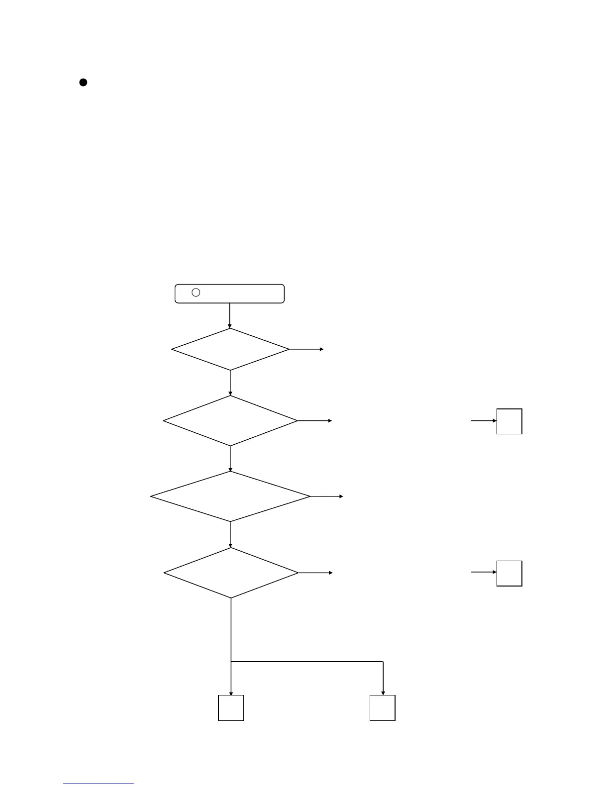
[no picture, no sound]
C onfirm the LED state and examine according to the following Flowcharts:
LED does not light.
Are the voltages of
pin1/2/3(+5.6V) of PPM2
connector of MAIN PCB
normal?
Change MAIN PCB or EPM1 (cable).
If no improvement, go to
Power Supply Unit Troubleshooting
No
Yes
Is AC Fuse
F9A2 T6.3AH 250V of Filter
PCB normal?
Change AC Fuse of Filter PCB
Are the voltages of
pin6(+5.0V)/7(+3.3V) of PPM1
connector of MAIN
PCB normal?
Yes
Yes
Yes
No
No
No
Change MAIN PCB or EPM1 (cable)
Is the voltage of pin1(+5.0V)
of PPM1 connector of MAIN
PCB normal?
Change MAIN PCB or EPM2 (cable).
If no improvement, go to
Power Supply Unit Troubleshooting
Go to Picture Troubleshooting
Go to Sound Troubleshooting
B C
A
A
1
 Loading...