Hitachi VSP User and Reference Guide
1–4
Introduction
Controller chassis
The controller chassis (factory designation DKC) includes the logical
components, memory, disk drive interfaces, and host interfaces. It can be
expanded with a high degree of granularity to a system offering up to twice
the number of processors, cache capacity, host interfaces and disk storage
capacity.
The controller chassis includes the following maximum number of
components: two service processors, 512 GB cache memory, four grid
switches, four redundant power supplies, eight front-end directors, four
back-end directors, and ten dual fan assemblies. It is mounted at the
bottom of the rack because it is the heavier of the two units. If a system has
two SVPs, both SVPs are mounted in controller chassis #0.
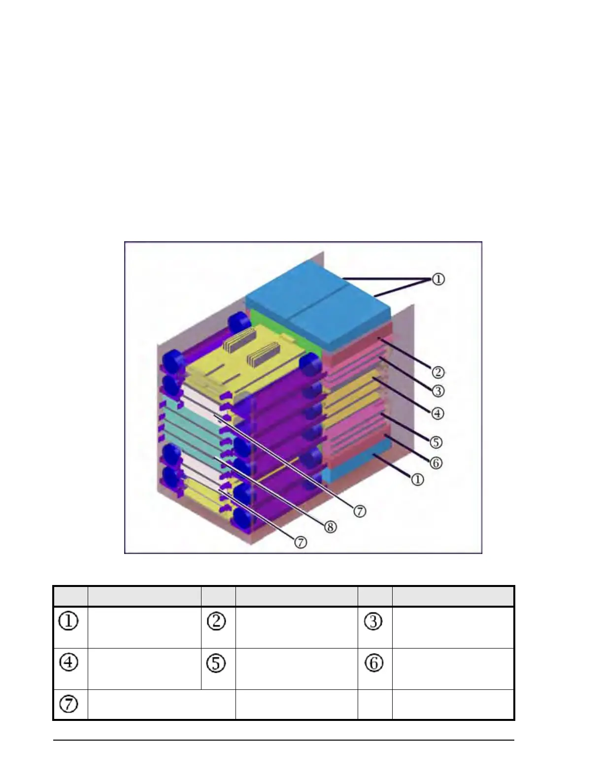
The following illustration shows the locations of the components in the
controller chassis. The controller chassis is described in more detail in
System Components on page 3-1.
Figure 1-2
Item Description Item Description Item Description
Power Supply
2, 3 or 4 units per
controller
Service Processor
One or two units in the #0
controller chassis.
FED (front-end director)
Grid switches FED (up to 8, and
BED (back-end director)
(up to 4)
Cache (2 to 8 boards)
Virtual Storage Directors
(2 to 4 microprocessor boards)
 Loading...