QUICK START GUIDE
HITRON
CGNVM
Connect to the network
Connect to the telephone
Set up your wireless network
Read me
first!
1
STEP
Check the Box Contents
Look in the box and make sure you have the following:
2
STEP
Connect to a Cable Outlet
Use a coaxial cable (not included) to connect the device’s CABLE
connector to a cable outlet.
3
STEP
Connect to a Power Outlet
Use the power cord provided to connect the POWER port to a power
outlet.
6
STEP
4
STEP
5
STEP
User Configuration (Optional)
QUICK START GUIDE
HITRON CGNVM
ETHERNET CABLE
POWER CORD
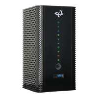
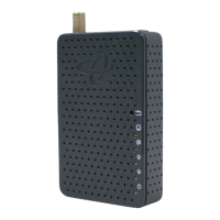
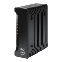
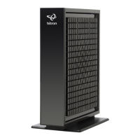
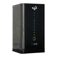
The Hitron CGNVM is an application gateway that provides wired and
wireless high-speed Internet access as well as MoCA (Multimedia over Coax
Alliance) networking to the Ethernet-enabled devices in your home for a
fast and easy home entertainment network.
Use the Ethernet cable provided to connect one of the LAN ports
to an Ethernet-equipped device.
)
&
&
,
'
8
3
&
*
1
9
0
,
&
$
&
*
1
9
0
M
A
D
E
I
N
C
H
I
N
A
I
n
put
:
10
0-
12
0
V,
0.
5A
,
5
0
-
60H
z
P/
N
:
0
1
23
4
5
67
8
9
A
B
S/N:
AB123
4
5
6
7
8
9
0
C
M
M
AC:
AB987
6
5
4
3
2
1
0
e
M
T
A
M
AC: 1
2
3
45
67
89
A
B
M
o
d
e
l
Na
m
e
:
XXXXX-
XXXX
SSID
-
2
.
4G
:
YZ
1
2
3
45
6
7
89
0
Pas
s
Ph
r
a
s
e
:
9
8
76
5
4
3
21
0
YZ
SSID-
5
G
:
YZ
1
2
34
5
6
78
9
0
Use a telephone cable (not included) to connect one of the LINE
ports to a telephone device. Do this only if you have ordered
telephone service.
Connect to an Ethernet-Equipped Device (Optional)
Connect to a Telephone Device (Optional)
Connect with Wireless Devices (Optional)
In a web browser, enter 192.168.0.1 in the address bar followed by
Username and Password, as below.
cusadmin
password
7
STEP
Connect your wireless devices with the correct SSID and Passphrase.
If you have not changed them, the default values are indicated on
the sticker on the back of the unit.
)&
&
,
'
8
3
&
*
1
9
0
,
&
$
&
*
1
9
0
M
A
D
E
I
N
C
H
I
N
A
I
nput
:
1
00-
120
V
,
0
.
5
A
,
5
0-
6
0H
z
P/N:
0
1
2
34
5
6
78
9
A
B
S/
N
:
AB123
4
56
7
8
90
CM
M
A
C:
AB987
6
54
3
2
1
0
e
M
T
A
M
A
C:
12
34
56
7
8
9
A
B
M
o
d
e
l
N
a
m
e
:
XX
XXX-
XXXX
SSI
D
-
2.
4
G
:
YZ
1
2
34
5
67
8
9
0
Pas
sPhr
as
e
:
9
8
7
6
54
3
2
1
0
YZ
SS
I
D
-
5
G
:
YZ
1
2
3
4
56
7
8
9
0
)
&
&
,
'
8
3
&
*
1
9
0
,
&
$
&
*
1
9
0
M
A
D
E
I
N
C
H
I
N
A
I
np
ut
:
1
0
0-
120
V
,
0.
5A
,
50-
6
0
H
z
P/N:
0
1
2
34
56
7
8
9AB
S/N:
A
B1
2
3
45
67
89
0
C
M
M
A
C:
AB
9
8
76
5
43
21
0
e
M
T
A M
A
C:
12
3
4
5
67
8
9
AB
M
o
d
e
l
N
a
m
e
:
XXXXX-
XXXX
SSID-
2.
4
G
:
YZ12
3
45
6
7
8
9
0
Pa
ss
Phr
a
s
e:
98
7
6
54
3
21
0
YZ
SSID-
5
G
:
YZ12
3
45
6
7
8
90
)
&
&
,
'
8
3
&
*
1
9
0
,
&
$
&
*
1
9
0
M
A
D
E
I
N
C
H
I
N
A
I
n
put
:
1
00-
12
0V
,
0.
5A
,
50
-
6
0H
z
P/N:
0
1
2
3
45
6
7
89
AB
S/N:
AB
1
2
3
45
6
7
890
CM
M
AC
:
AB987
654
3
2
1
0
e
M
T
A
M
AC
:
12
34
5
6
78
9AB
M
o
d
e
l
Na
m
e
:
XXXXX-XXXX
SSID-
2
.
4G
:
YZ12
3
4
5
6
789
0
Pas
sPhr
a
s
e:
9
8
76
54
321
0
YZ
SSID
-
5
G
:
YZ123
4
5
67
8
90
Connect your wireless devices with the WiFi
Protected Setup (WPS). Access the configuration
interface (see step 6), enter the Wireless page
to enable WPS and set Encrypt Mode to AES,
then press Save Changes.
Press this button to begin the WPS Push-Button
Configuration (PBC) procedure. Press the PBC
button on your wireless clients in the coverage
area within two minutes to enable them to join
the wireless network.