22
3. ENG INE
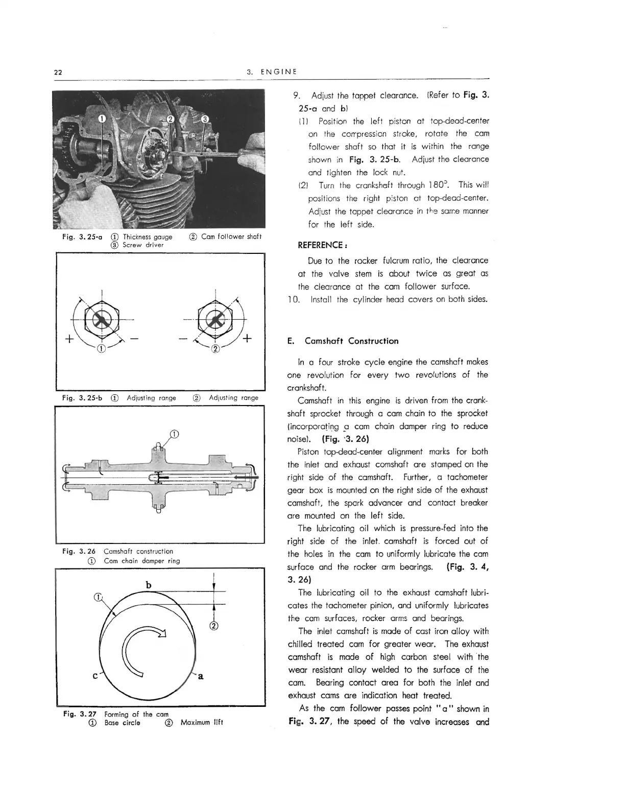
Fig . 3. 25-a CD Thickness gauge
@ Scr ew driver
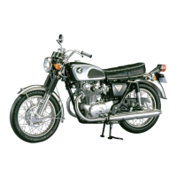
Fig . 3. 25-b CD Adj usting range
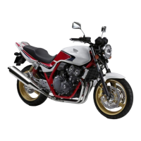
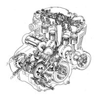
Fig. 3. 26 Camshaft construction
CD Com chain damper ring
b
C
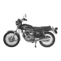
Fig. 3. 27 Forming o f the com
@ Cam fo llowe r shaft
@ Adjusting range
2
a
CD Base circle @ Ma ximum lift
9. Adiust the tappet clearance. !Refer to Fig. 3.
25-o and bl
111 Position the left piston at top-dead-center
on the corr pression stroke, rota te the cam
fol low er shaft so that it is wi thin the range
shown in
Fig. 3. 25-b . Adjust the clearance
and tighten the lock nut.
(21 Turn the
cranksheift through 180~. This w ill
positions the right piston at top-dead-center.
Adiust the tappet clearance in
the sarr.e manner
for the lef t side.
REFERENCE:
Due to the rocker fulcrum ratio , the clearance
at the valve stem is about tw ice as great as
the clearance at the cam fo llow er surfcce.
1 0. Install the cylinder head covers on both sides.
E. Camshaft Construction
In a four stroke cycle engine the camshaft makes
one revolutio n for every two revolut ions of the
crankshaft.
Camshaft in this engine is driven from the crank-
shaft sprocket through a cam chain to the sprocket
(incorporating
5J cam chain damper ring to reduce
noise!.
(Fig. ·3. 26)
Piston top-dead-center alignment marks for both
the inlet and exhaust camshaft are stamped on the
right side of the camshaft. Further, a tachometer
gear box is mounted on the right side of the exhaust
camshaft, the spark advancer and contact breaker
are mounted on the left side.
The lubricating oil which is pressure-fed into the
right side of the
inlet camshaft is forced out of
the holes in the cam to uniformly lubricate the cam
surfac e and the rocker arm bearings.
{Fig. 3. 4,
3. 26)
The lubricat ing oil to the exhaust camshaft lubri-
cates the tachometer pinion, and uniformly lubricates
the cam surfaces, rocker arms and bearings.
The inlet camshaft is made of cast iron alloy with
chilled treated cam for greater wear. The exhaust
camshaft is made of high carbon steel with the
wear resistant alloy welded to the surface of the
cam. Bearing contact area for both the inlet and
exhaust cams are indication heat treated .
As the cam follower passes point "a" shown in
fi G, 3. 27, the speed of the valve increases and