©2018 American Honda Motor Co., Inc. Page 3 of 6
5. INSPECTION
Perform a visual inspection of the GCU and inverter. Component inspection is listed in the order in which they need to
be removed to access the next component.
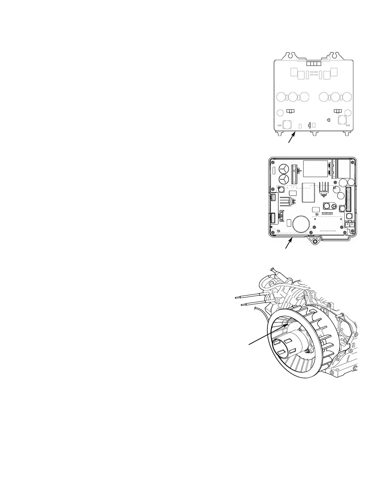
Inverter: To visually inspect the inverter, remove the front cover and the control
panel. Visually inspect the back of the inverter for any discolored or damaged wiring,
capacitors, or connectors, and note any bubbling, corrosion, or other unusual
conditions. If any of these issues are present, the inverter is likely faulty.
While the inverter may be faulty, it may not be the cause for the overall generator
failure. Some other circumstance, or other component failure, may have caused the
inverter to fail. Test the stator (see below) before contacting Techline or your DSM
for further instruction.
GCU: With the front cover and the control panel removed, visually inspect the circuit
board on the backside of the GCU for any discolored spots, deterioration,
contamination, or deformed capacitors.
Stator: The output and resistance tests performed in the
Generator Troubleshooting Guide or the appropriate shop manual
should be enough to determine if the stator is good or not. The
stator resistance readings should be consistent. If there is more
than 0.2 Ω of difference between readings, the stator has failed.
To visually inspect the stator, remove the spark plug, inverter, and
recoil starter, and then rotate the cooling fan until you can look
through the rotor windows at the stator windings. Rotate the rotor
by hand and slowly look for any signs of overheated or discolored
stator windings.
INVERTER
GCU
ROTOR
WINDOW