C
Carmen MerrittJul 26, 2025
What to do if Honda GX35 switch is OFF?
- DDavid WalkerJul 26, 2025
If your Honda Engine won't start, and the engine switch is OFF, turn the engine switch to the ON position.
 Loading...
What to do if Honda GX35 switch is OFF?
If your Honda Engine won't start, and the engine switch is OFF, turn the engine switch to the ON position.
What to do if Honda Engine is out of fuel?
If your Honda Engine won't start, make sure it has fuel. If it is out of fuel, refuel it.
What to do if Honda GX35 has bad fuel?
If your Honda Engine won't start because of bad fuel (engine stored without treating or draining gasoline, or refueled with bad gasoline), drain the fuel tank and carburetor and refuel with fresh gasoline.
What to do if Honda GX35 spark plug is wet?
If your Honda Engine won't start and the spark plug is wet with fuel (flooded engine), allow the spark plug to dry. After drying, install the spark plug and start the engine.
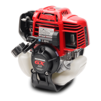
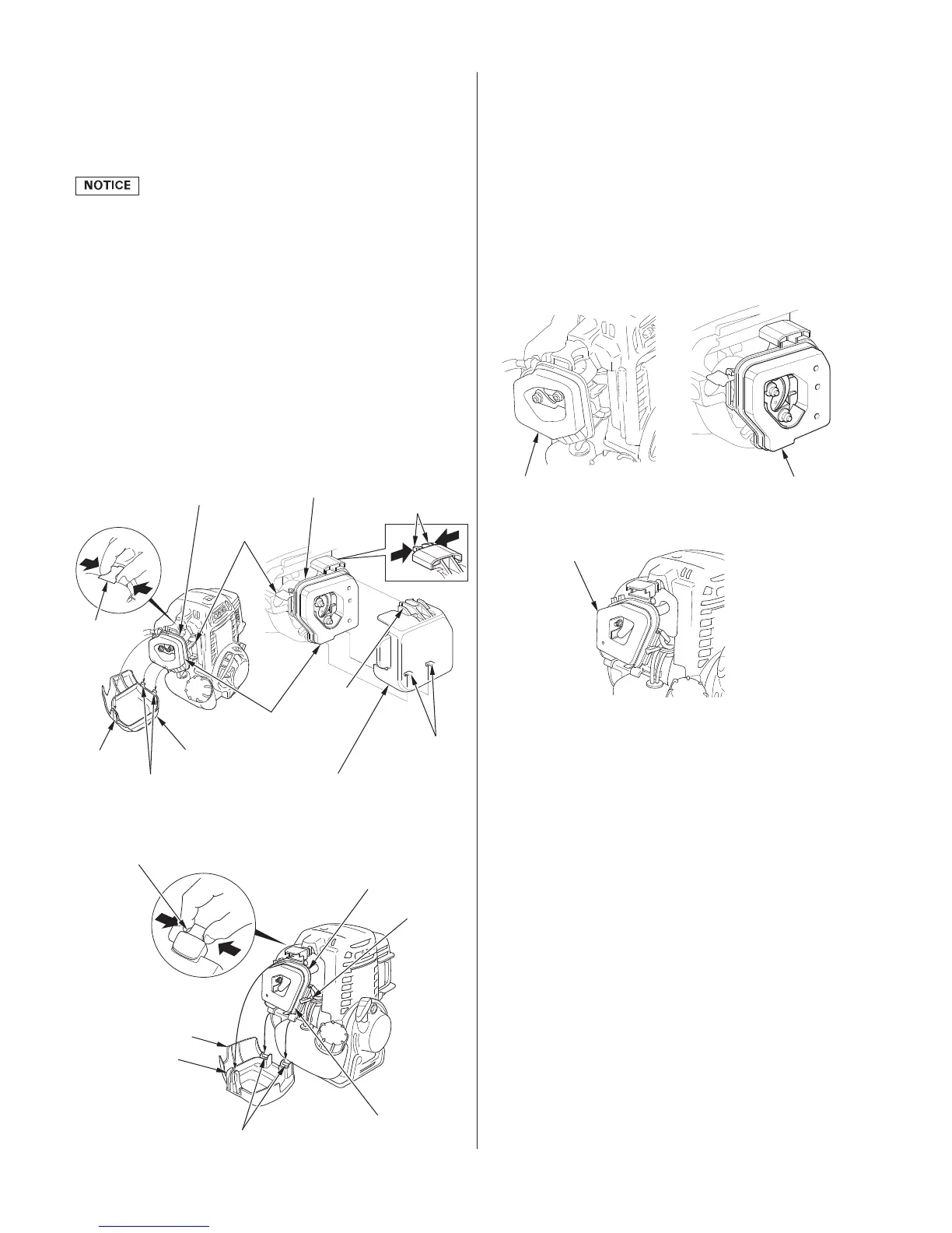
What to do if Honda GX35 Engine filter element is restricted?
If your Honda Engine lacks power and the filter element is restricted, clean or replace the filter element.
| Compression Ratio | 8.0:1 |
|---|---|
| PTO Shaft Rotation | Counterclockwise (from PTO shaft side) |
| Ignition System | Transistorized magneto ignition |
| Starting System | Recoil starter |
| Air Cleaner | Semi-dry type |
| Lubrication System | Oil mist |
| Displacement | 35.8 cm³ |
| Bore x Stroke | 39 mm x 30 mm |
| Net Power Output | 1.3 hp (1.0 kW) at 7, 000 rpm |
| Net Torque | 1.6 Nm (1.2 lbs ft) at 5, 500 rpm |
| Fuel Tank Capacity | 0.63 liters |
| Oil Capacity | 0.1 liters |
| Dry Weight | 3.3 kg (7.3 lbs) |
Provides warnings about potential hazards that could hurt you or others.
Safety advice to prevent injury from exhaust fumes and operational hazards.
Step-by-step instructions for starting a cold or warm engine.
Explains why regular maintenance is crucial for safe, economical operation.
Highlights critical safety precautions when performing maintenance.
Warnings against tampering with the emission control system.
How to operate the auger for best results, including pressure and cutting advice.
Instructions for checking and adding fuel and oil before first use.
Specific instructions for mixing 2-cycle oil and fuel for the engine.