Do you have a question about the Honda HT3813 and is the answer not in the manual?
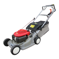
| Engine Type | GC130 4-stroke gasoline |
|---|---|
| Engine Displacement | 133 cc |
| Cutting Height | 25-75 mm (1-3 in), 6 positions |
| Weight | 29 kg (64 lbs) |
| Cylinders | 1 |
| Fuel Tank Capacity | 1.0 L (0.26 US gal) |
| Deck Material | Steel |
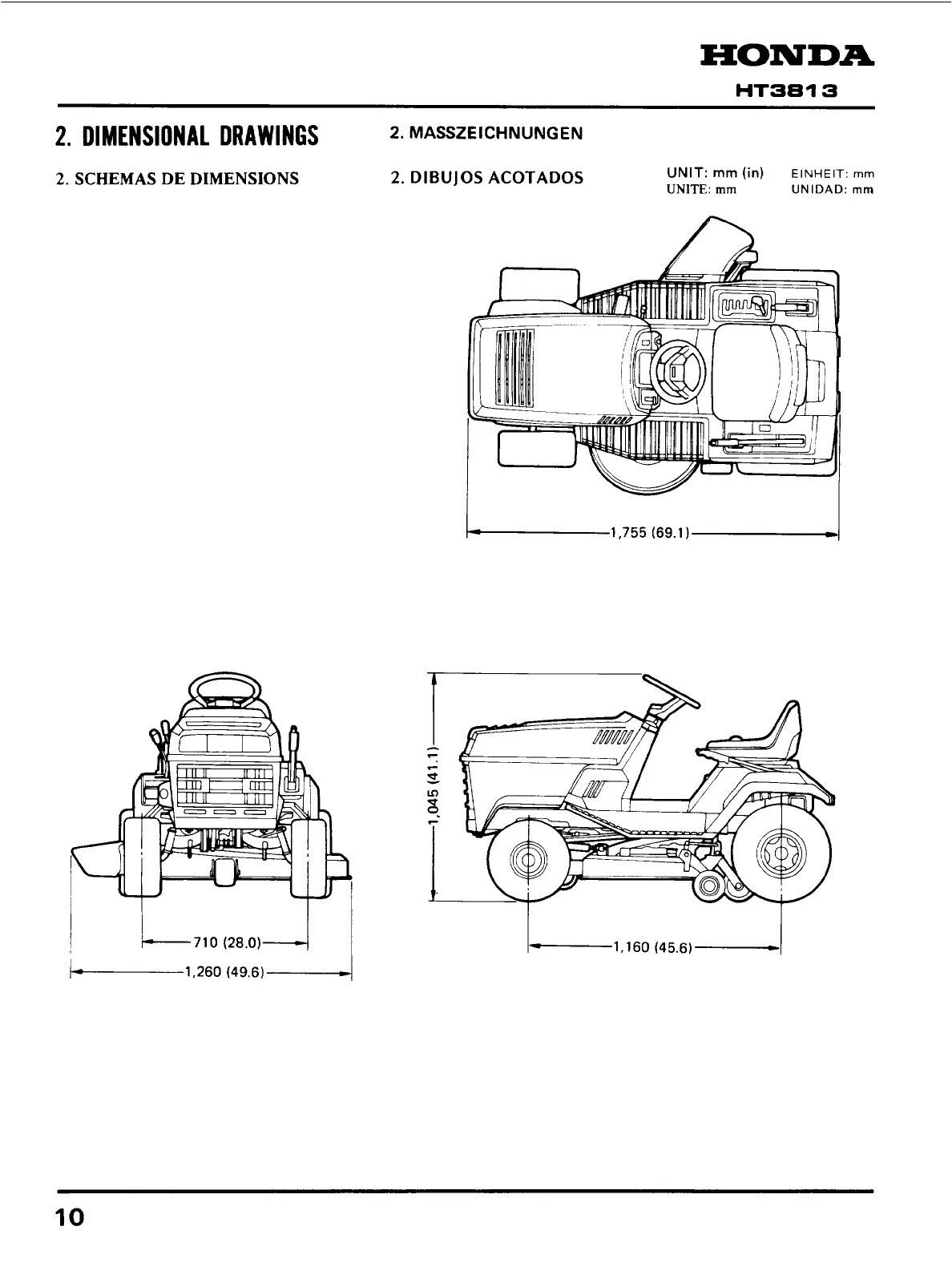
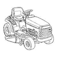
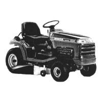
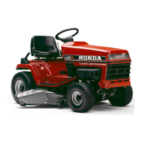
Details dimensions and weight specifications for different models.
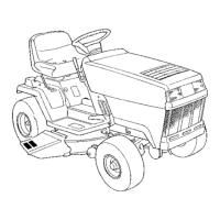
Illustrates the overall dimensions of the tractor with key measurements.
Provides essential safety precautions and warnings for operation.
Outlines rules and guidelines for performing service and maintenance.
Identifies the locations of serial numbers on the engine and frame.
Lists standard maintenance specifications and service limits for various components.
Specifies torque values for critical fasteners during assembly and repair.
Lists and illustrates special tools required for maintenance and repair procedures.
Details engine oil type, capacity, and inspection procedures.
Provides coolant type, capacity, and replacement instructions.
Explains air cleaner inspection, cleaning, and replacement.
Provides diagnostic flowcharts and solutions for common engine problems.
Outlines regular service intervals and tasks for maintaining the tractor.
Illustrates the routing of electrical cables and harnesses on the tractor.
Shows the electrical system wiring for troubleshooting and repair.
Identifies safe points for lifting and supporting the tractor.
Details inspection and adjustment of the brake pedal clutch cable.
Explains how to check and adjust shift lever free play.
Instructions for inspecting and adjusting the damper.
Covers disassembly, inspection, and reassembly of the drive clutch.
Details the clutch arm stopper bolt adjustment procedure.
Instructions for inspecting and replacing brake shoes.
Covers the adjustment procedure for the brake pedal rod.
Explains inspection and function of parking brake, lamp, and buzzer.
Details the seat safety switch inspection.
Instructions for replacing the headlight bulb.
Covers inspection and replacement of the cutter deck drive belt.
Details blade belt inspection and replacement.
Instructions for checking and tightening blade bolts.
Covers front axle inspection and maintenance.
Instructions for cleaning the radiator screen.
Covers engine disassembly and reassembly procedures.
Details the disassembly and reassembly of the cutter deck assembly.
Explains the disassembly and reassembly of the drive clutch.
Covers the disassembly and reassembly of the brake system.
Details the disassembly and reassembly of steering and wheel components.
Describes the power train system and its components.
Explains the mechanical auto-clutch transmission mechanism.
Details the steering mechanism and its components.
Covers the front axle assembly and its function.
Explains the brake system operation and components.
Describes the overheat alert system and its function.
Details the side discharge mechanism for grass.