7
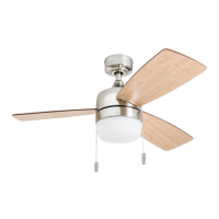
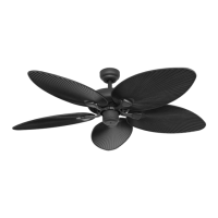
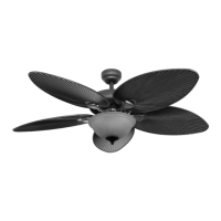
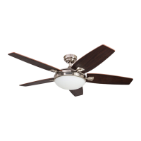
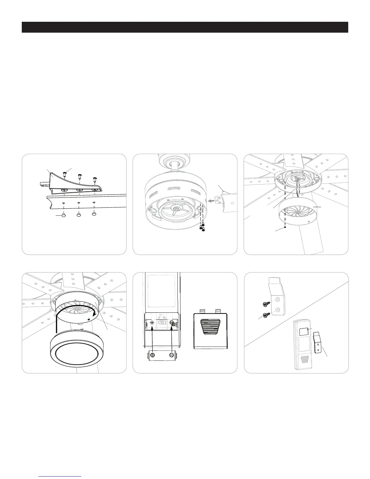
FINAL INSTALLATION
Figure 5.5
Figure 5.8 Figure 5.9
Figure 5.4
Figure 5.7
Figure 5.6
Blade Screw
Screw Cap
Blade Arm
Blade Arm
Motor Screw
Lens Cover
Light Kit
Battery
Battery Door
Wall Bracket
Wall Bracket
Slot
Wall Bracket
Screw
Light Kit
Single-pin
Connector
Fitter Plate
Screw
Blade
4. Partially insert three blade screws through the blade arm and the blade. Secure each blade screw with a blade screw cap, starting
with the one in the middle. Repeat this step for the remaining blades and blade arms (Figure 5.4).
5. Insert blade arm (K) through slots in the side of the motor assembly. Align the holes of one blade arm with two motor screw
holes in underside of the motor assembly. Secure with two motor screws. Repeat this step for the remaining blade arms
(Figure 5.5).
6. Remove one of the three fitter plate screws preassembled to the fitter plate and loosen the other two but do not remove.
Connect the single-pin connector from the fitter plate to the single-pin connector from the light kit -- Blue to Black and
White to White. Align the slotted holes in the light kit with the loosened screws in the fitter plate. Turn light kit clockwise and
replace the previously removed fitter plate screw. Tighten all screws (Figure 5.6).
7. Attach the lens cover to the light kit by twisting the lens cover tightly in a clockwise direction (Figure 5.7).
8. Remove the battery cover from the back of the remote transmitter and insert the 12-volt battery, noting polarity -- positive (+)
to positive (+) and negative (-) to negative (-). Replace the battery cover. If battery is installed correctly, the LED indicator on
the front of the remote transmitter should illuminate when any button is pushed (Figure 5.8).
9. (Optional) If you wish to install the wall bracket for the remote, insert the two screws through the wall bracket and into the
wall. Once the wall bracket is installed, hang the slot in the back of the remote over the top of the wall bracket (Figure 5.9).
Turn on power to fan at breaker box and the wall switch. Assembly is complete.
 Loading...