6
FINAL INSTALLATION
Figure 4.2
Figure 5.2
Figure 4.1
Figure 5.1
Figure 4.3
Figure 5.3
Mounting
Bracket Screw
Canopy Cover
Closemount
Screw
Mounting
Bracket
Canopy
Canopy
Canopy
Receiver
Hook
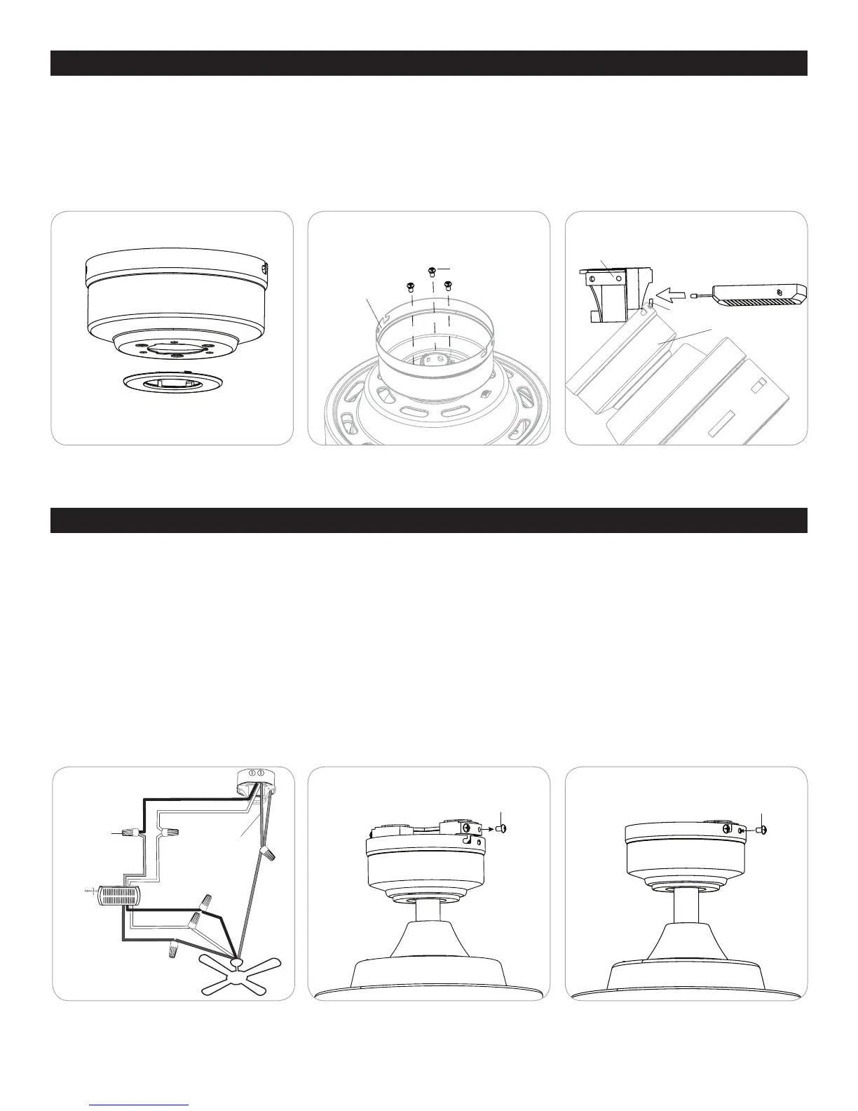
CLOSEMOUNT INSTRUCTIONS (optional)
1. Remove the canopy cover from the bottom of the canopy (Figure 4.1).
2. Remove the three Phillips-head closemount screws from the top of the motor assembly. Then align the canopy with the holes
in the top of the motor assembly. The larger holes in the canopy will encompass the remaining screws. Secure the canopy to
the top of the motor assembly with the previously removed closemount screws (Figure 4.2).
3. Raise the motor assembly and place the canopy on the hook of the mounting bracket to free hands during the wiring process
(Figure 4.3). Then, insert the receiver into the opening of the mounting bracket.
Mounting
Bracket Screw
WARNING: Do NOT wire the
fan motor to a variable-speed
(dimmer) wall control.
1. Use wire connnectors to connect household supply and fan wires according to the diagram (Figure 5.1) and the following
steps:
• Connect the green wire from the downrod and mounting bracket to the Bare/Green (ground) supply wire. Note: Closemount
installation does not use the downrod, so there will only be two Green wires to connect.
• Connect the White wire with red label from the receiver to the White (neutral) supply wire.
• Connect the Red wire with red label from the receiver to the Black (hot/power) supply wire.
• Connect the Black wire with white label from the receiver to the Black fan wire.
• Connect the Blue wire with white label from the receiver to the Blue fan wire.
• Connect the White wire with white label from the receiver to the White fan wire.
2. Align the canopy over the loosened mounting bracket screws. Place the J-slot of the canopy onto the mount bracket screws
and rotate clockwise (Figure 5.2).
3. Secure the canopy with the two previously removed mounting bracket screws. Tighten all the mounting bracket screws
securely (Figure 5.3).
Wire
Connector
Black (hot/power)
White (neutral)
Bare/Green
(ground)
Red
White
White
White
Black
Blue
Blue
Black
Green
Green
Receiver
 Loading...