– 3 –
WIRING FOR OPTIONAL FEATURES AND APPLICATIONS
Summary of Harness Wire Functions
Purpose Wire Color Function
Red Keypad Red or Aux (+12VDC)
Black Keypad Black or Aux (–)
Green Keypad Green (control Data In); Not Used on GE Caddx NX panels
Keypad
Connections
Yellow Keypad Yellow (control Data Out)
Purple LED Status Light Purple wire (Green light)
LED Status
White/Purple LED Status Light white/purple (Red light)
Blue/Green Channel 4 N/C (5amp)
Brown/White Channel 4 N/O (5amp)
Relay Output
Button
Brown Channel 4 Common (5amp)
White Channel 3 Common (Garage Door Pushbutton) Garage Door
Opener
Red/White Channel 3 N/O relay (Garage Door Pushbutton)
Entry/Exit zone Gray Channel 1 (-) momentary output
Wiring the Status LED
The status LED is a low voltage type and must be
wired to the Code Encryptor 3. If you attempt to
connect it any other way, the LED will burn out and
will NOT operate again.
Status LED Indications
LED Action Indication
Red LED Flashing Away mode
Red LED Solid Stay mode
Green LED Flashing Not Ready
Green LED Solid Ready
Yellow LED Flashing Rapidly Alarm occurred
CE3-004-V1
PURPLE (LIGHTS LED GREEN)
BLACK (COMMON)
WHITE / PURPLE (LIGHTS LED RED)
CODE
ENCRYPTOR 3
RECEIVER
STATUS
LED
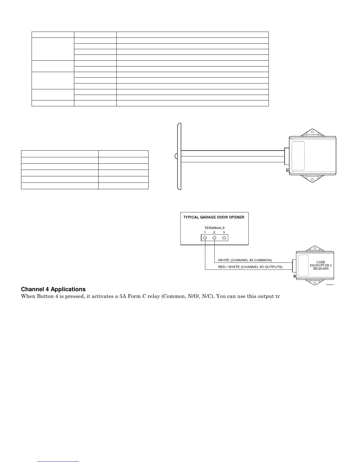
Wiring to a Garage Door Opener (Channel 3 Application)
When button 3 is pressed, it activates a momentary contact closure for opening and closing a garage door. Occasionally, you may want
to use Channel 3 for control of other optional accessories (i.e., garage door motor, Malibu lighting, sprinklers, X-10 automation).
All garage doors have a wall mounted push button that
activates the door via a two-wire connection. Make your
connection at the push button switch or at the garage door
motor where these two wires terminate. Connect the red/white
and white wires from the CE3 to these two wires as shown. If
you choose to connect to the motor, trace the wires from the
push button to the motor and determine the proper connection
point. Most garage doors (except MOM Crusader models) use
terminals #1 and #2. For MOM Crusader models, use
terminals #2 and #3.
CE3-005-V0
TYPICAL GARAGE DOOR OPENER
TERMINALS
WHITE (CHANNEL #3 COMMON)
RED / WHITE (CHANNEL #3 OUTPUTS)
CODE
ENCRYPTOR 3
RECEIVER
2 31
Channel 4 Applications
When Button 4 is pressed, it activates a 5A Form C relay (Common, N/O/, N/C). You can use this output trigger for a 2nd garage
door motor, or any device controlled by a momentary relay output.
Default Mode
When the Code Encryptor 3 is not connected to the data bus of a control panel, it acts as a 2-relay module.
Button 1 triggers Channel 3 - Relay 1 (momentary).
Button 2 triggers Channel 4 - Relay 2 (momentary).
Channel 1 Momentary (-) Output (Optional)
When you momentarily press button 1 on the Code Encryptor 3 remote, the Gray wire momentarily sends a 500ma (-) output.
You can use this output to trigger an exit/entry zone to ensure the panel goes into Away mode.
PANIC MODE
Press and hold buttons 1 and 2 on the remote control for police panic. This will cause the panel to go into a panic mode. Cancel
Panic at a keypad. THE REMOTE WILL NOT CANCEL A PANIC.
Activating panic mode
NOTE: This is the default setting of the Code Encryptor 3.
If you have previously programmed remote panic “OFF” and would like to turn it back “ON” follow the steps below. If this is a
new installation, Panic “ON” is the DEFAULT setting for the Code Encryptor 3.
1. Unplug the wire harness from the Code Encryptor 3.
2. Press and HOLD the program button.
3. While HOLDING the program button, plug the Code Encryptor 3 harness back in. The LED located on the front will turn ON.
4. Immediately release the program button. Auto recognition will start.
IF NECESSARY, PROGRAM THE ALARM PANEL FOR KEYPAD PANIC.
 Loading...