Installation and Operations Guide
|
Hardware installation
© Honeywell. All Rights Reserved. LT-VLXEXPAXMIOG Rev. 01
31
a single VLX/ACM-VLX in a multi-drop configuration. See Figure 8 on page 12
for a wiring diagram.
CAUTION Software references data in EXPs/AXMs by EXP/AXM address.
Ensure that the addresses you set comply with engineering schematics and
planned sequences of operation. See “Identifying input and output objects” on
page 58 for more information about referencing EXP data.
Ethernet
Ethernet is a high-speed LAN widely installed in commercial buildings. Ethernet
is the preferred method of connecting the VLX/ACM-VLX to a BACnet
internetwork.
Terminal identification VLX: Terminals for the EXP/AXM
communications bus are on the lower right,
labeled EXP COMM + and EXP COMM –. On
EXPs/AXMs, terminals are on the upper right,
labeled COMM + and COMM –.
ACM: Connection is based on where the 485
option card is plugged in that the ACM-VLX will
use.
Cable type and length Use 18AWG two conductor twisted shield cable.
Maintain polarity throughout the EXP/AXM
communications bus. Distance between units—
VLX-to-EXP, VLX-to-AXM, ACMVLX-to-
EXP, ACMVLX-to-AXM, EXP-to-EXP, EXP-
to-AXM, and AXM-to-AXM—cannot exceed
10ft. (3.048m) between devices.
Terminating resistors Matched precision resistors are required at each
end of the bus. Wire the resistors across + and –.
Typical resistance value is 120 Ohm.
Shield grounding Terminate shield drain at VLX/ACM-VLX end to
panel ground. Tie shield drain through with wire
nut at each intermediate EXP/AXM. Tape shield
drain back at last EXP/AXM.
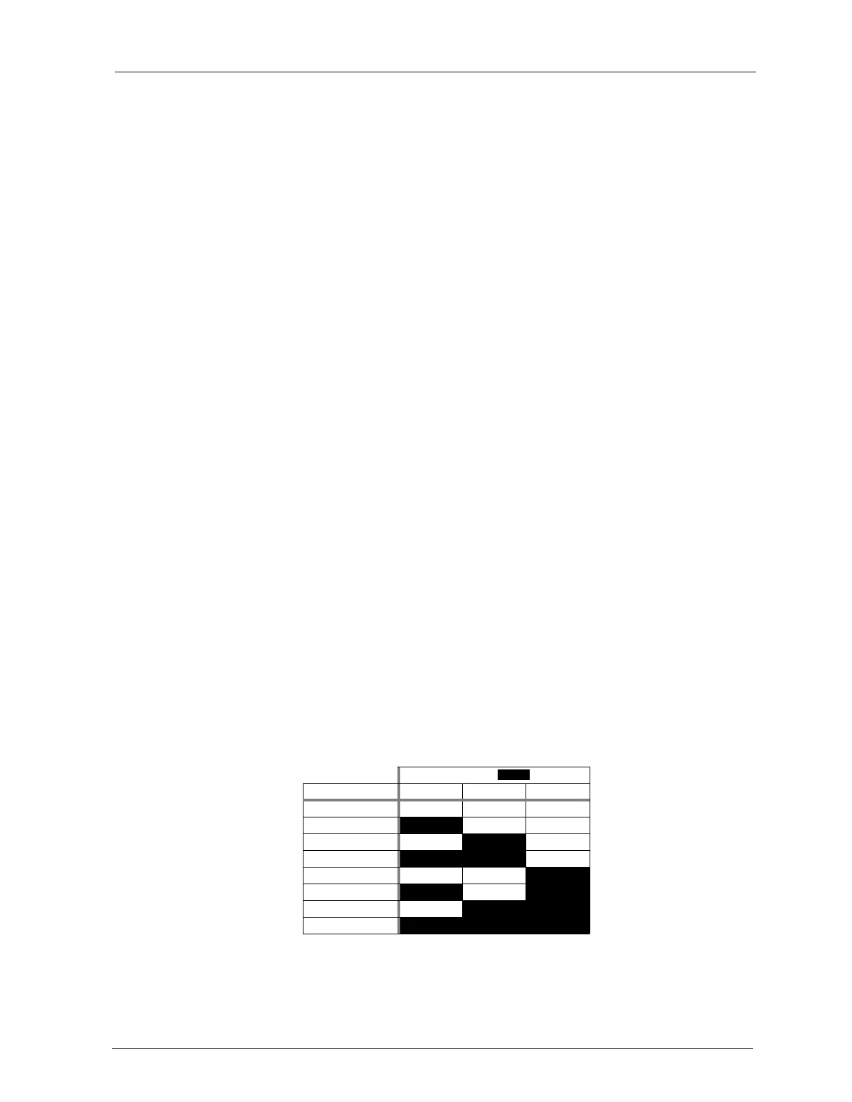
EXP addressing Each EXP/AXM on the communications bus has
a unique address from 0–7. Use the DIP-switch
bank labeled SW1 on the left of the EXP/AXM to
set the address. Use DIP switches 1–3 for
addressing (switch 4 is not used for addressing).
Table 5 DIP SW1 s e ttings for EXP/AXM address e s
DIP Po s itio n ( = ON)
EXP Addres s 1 2 3
0
1
2
3
4
5
6
7
 Loading...


