65-0156—1 6
C7024E,F
INSTALLATION
Fig. 4—Example of flame discrimination
problem (opposed burners).
M1957
DETECTOR A
FLAME A
DETECTOR B
FLAME B
Sight pipes with diameters 2 to 3 in. [51 to 76 mm]
pro-duce better results for horizontal rotary burners,
which require wide viewing angles. A wide viewing
angle can also be obtained by using a short sight pipe.
Prepare Hole in Wall of Combustion Chamber
At the selected location, cut or drill a hole the proper
diameter for the sight pipe into the wall of the combustion
chamber. Flare the hole to leave room for small adjust-
ments of the sighting angle. The taper of the hole should be
about 1 in. for every 3 in. [25 mm for every 76 mm] of wall
thickness.
Mount Sighting Pipe
Thread one end of the pipe to fit the mounting flange,
union, or required coupling. Cut the pipe to the desired
length (as short as practicable) and at an angle so it fits
flush with the wall of the combustion chamber. Tack
weld the pipe to the wall in a trial position. Do not weld
the sighting pipe permanently in place until after com-
pleting the Adjustments and Checkout section.
NOTE: If you use part no. 118367A Swivel Mount and
you are positive about the location and sighting angle,
permanently weld the pipe.
Install Fittings
In some cases, the sight pipe will not directly fit the
C7024 Mounting Flange or union. Also, it may be desir-
able or necessary to vent the sight pipe. You may also
want to use a swivel mount or an antivibration mount.
Each of these cases may require additional fittings.
Reducer
For sight pipes of larger diameter than the mounting
flange connector or union, install a reducer as illustrated
in Fig. 5. The reducer will require a close nipple with
these external threads:
C7024E: 3/4 in. NPT.
C7024F: 1 in. NPT.
Fig. 5—Typical mounting of C7024.
1
CLOSE NIPPLE
(3/4 in. FOR
A C7024E; 1 in.
FOR A C7024F.
TEMPORARY
TACK WELD
COMBUSTION
CHAMBER WALL
REDUCER
BLACK IRON SIGHT
PIPE (1-1/2 TO 3 in.
[38 TO 76 mm] DIA.)
REFRACTORY
FLARED
HOLE
1
IF VENTILATION OF THE SIGHTING PIPE IS REQUIRED, ADD PIPE
TEE, PERFORATED NIPPLE, OR OTHER SUITABLE DEVICE
FOR VENTILATION.
M1958A
SIGHT PIPE VENTILATION
It may be necessary to ventilate the sight pipe to cool
the detector or to clear a viewing path through UV
radiation attenuating material.
For a negative pressure combustion chamber, drilling
a few holes in the section of the sight pipe outside the
combustion chamber will allow air at atmospheric pres-
sure to flow through the sight pipe into the chamber. A
perforated pipe nipple between the sight pipe and the
detector can also be used.
For a positive pressure combustion chamber, connect
a supply of pressurized air from the burner blower to
flow supply through the sight pipe into the chamber. The
air pressure must be greater than the chamber pressure.
SWIVEL MOUNT
To facilitate proper flame sighting, part no. 118367A
Swivel Mount is available. The swivel mount will re-
quire a reducer of the proper size to mount it onto the
sight pipe. It will also require a one-inch close nipple for
mounting to a C7024 with a one-inch connector. For
mounting details for the 118367A Swivel Mount, refer
to form 60-0361.
ANTIVIBRATION MOUNT (C7024E)
The detector will withstand normal burner vibra-
tion. If the vibration is excessive, part no. 123539
Antivibration Mount is available for the C7024E. (For
mounting details, see form 60-0361.) If you use this
mount, install it before positioning and sighting the
detector.
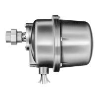
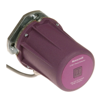
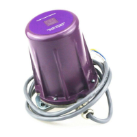
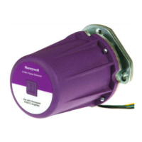
MOUNT THE DETECTOR
Mount the detector on the sight pipe, reducer, or other
fitting (see Figs. 6 to 9).
The C7024E,F Self-Checking Flame Detectors incor-
porate an oscillating shutter mechanism and therefore
require special consideration for mounting positions other
than vertically sighting downward or upward as illus-
trated in Fig. 6.