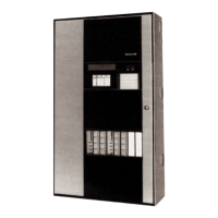
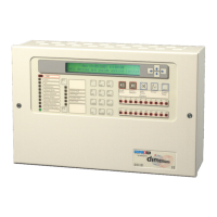
DELTANET FS90 OPERATING INSTRUCTIONS
Automation and Control Solutions
Honeywell International Inc. Honeywell Limited-Honeywell Limitée
1985 Douglas Drive North 35 Dynamic Drive
Golden Valley, MN 55422 Toronto, Ontario M1V 4Z9
www.honeywell.com/buildingsolutions
® U.S. Registered Trademark
© 2007 Honeywell International Inc.
74-5069 J.I. 11-07
Table 1. CA Board Switch and LED Functions.
MAINTENANCE PROCEDURES
The system must be maintained in accordance with the system
documentation and procedures and practices contained in applicable
NFPA and UL standards, including NFPA 70, 72, 90A, 92A and 92B.
DeltaNet FS90 Systems Maintenance and Repair Manual for further
details, including testing, fuse replacement and replacement parts.
For service, contact your local Honeywell Automation & Control
Solutions office as listed in the phone book, or contact a regional
office as shown at the end of this document.
This product may contain small amounts of chemicals
and substances that may be banned from disposal in
landfills. At the end of the useful life of this product, it is
the owners’ responsibility to safely decommission the
product and arrange for disposal in accordance with all
applicable environmental laws and regulations, including
Directive 2002/96/EC of the European parliament and the Council of
27 January 2003 on Waste Electrical and Electronic Equipment
(WEEE).
Switch/
LED Normal Operation Setup Mode
Micro-
Processor
Reset Switch
Resets microprocessor. Exits Setup Mode. Any changes made
during Setup Mode will be lost if this
switch is activated.
Acknowledge
/Silence
Switch
Acknowledges troubles and alarms or silences outputs as follows:
Acknowledge position (UP): The local audible silences and blinking LEDs change to
steady on. The Acknowledge/Silence switch does not affect indicating zone outputs or
silence alarm signals.
NOTE: Zones set up as central are acknowledged when the new status reports to
the central processor. FS90 acknowledgement of these zones is not required
unless communication with the central fails and stand-alone mode is in effect.
Silence position (DOWN): The indicating zone devices silence, the FS90 local audible
silences, the CA Board Silence LED turns on and blinking LEDs change to steady on.
NOTE: Operators may also silence zones set up as central from the central
processor.
Advances pointer to next function.
Reset Switch Resets FS90. The system removes power to all initiating zones for 15 seconds,
activates the CA Board reset out signal for 15 seconds and returns all input zone status
indicators and their associated outputs to normal. After the 15-second reset time any
zone(s) remaining in alarm or trouble annunciates as a new alarm or trouble.
Selects or deselects characteristics.
Panel Test
Switch
Initiates a test of all LEDs except the communication board transmit and receive LEDs.
The test turns on the LEDs and sounds the local audible. The test indicates that all
function boards are operational and controlled by the CA Board microprocessor. The
panel test does not affect alarm or trouble reporting in the system.
Enter characteristics into date file and
moves pointer.
Manual
Evacuation
Switch
Initiates a manual evacuation signal. All indicating zones turn on and a common alarm
indication and pulsing local audible occur (if audible is selected and the system is in the
stand-alone mode). Toggle the Acknowledge/Silence switch to silence the output and
then toggle the Reset switch to return the system to normal.
Not used.
Setup Switch Enters Setup Mode. Exits Setup Mode.
Alarm LED Indicates a common alarm in the system via blinking LED. Indicates the system is ready to enter
group address menu.
Trouble LED Indicates a common trouble via a blinking yellow LED. Indicates the system is ready to enter
code menu.
Silence LED Indicates the Silence switch has been activated to silence the outputs. Indicates the system is ready to enter
the special options menu.
Low Battery
LED
Indicates a low battery condition if system power supply is off. If a Battery Supervision
Module is installed, this LED indicates low battery or absence of batteries at all times.
Indicates various time menus when
used with ground fault and disconnect
LEDs.
Ground Fault
LED
Indicates a ground fault in the system. Indicates various time menus when
used with low battery and disconnect
LEDs.
Isolate LED Indicates one of the Disconnect switches on a module is activated or a point has been
isolated or locked out.
Indicates various time menus when
used with low battery and ground fault.
Power LED Indicates power is on. Indicates system is ready to enter
output menu.
Run LED Indicates system is ready to operate. Indicates system is ready to enter input
menu.
Setup LED Off On to show system is in Setup Mode.

 Loading...


