❶ Select the mounting location.
❹ Wire the unit.
❸ Mount the unit.
❺a Walk-test the sensor.
Mounting Location Guidelines
• 2.3 m mounting height.
• Avoid direct or reflected sunlight.
• Aim sensor away from windows, heating/cooling devices
or large moving objects.
• Sensor must have a clear line-of-sight to protected area.
• Use a small screwdriver to unfasten the housing latch. Gently pull
apart the housings.
• Push outward on the PCB latch and lift the PCB out of the housing.
• Slide the wire through the wire channel in the back housing.
• Mount the back housing flat against a wall or in a corner.
Note: If using the Rear Tamper feature, refer to the Rear Tamper
section before mounting the sensor.
• Replace the PCB.
• Apply power to the unit. Initialisation is complete when the
LED stops flashing slowly.
• Adjust the microwave range to minimum setting (25%) by
turning the range adjustment counterclockwise using a
small screwdriver.
• Replace the front housing.
• Begin walking through the detection area.
- The LED will turn red, indicating an alarm detection.
• Increase the microwave range as necessary.
• Repeat the items in step 5a until proper detection range is
obtained.
• The sensor MUST be walk tested after every power up
to complete the power up mask detection test.
❺b Optional: Walk-test using Zone Finder.
• Use a screwdriver to short the test pads.
• During the Zone Finder walk-test mode, the LED turns:
- green for one second for every PIR detection;
- yellow for two seconds for every microwave detec-
tion.
• Adjust the microwave range as necessary.
• Zone finder mode times out after ten minutes.
Corner
Mount
Holes
Wire Channel
Wall
Mount
Holes
75%
100%
25%
50%
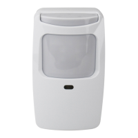
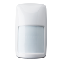
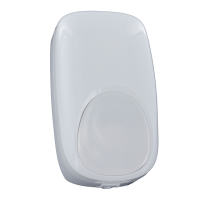
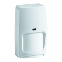
DT7550UK2 DUAL TEC
®
With Anti-Mask Motion Sensor Installation Instructions
Use the Zone Finder mode to identify the PIR and/or
microwave pattern. In Zone Finder mode the red
LED is disabled.
❷ Separate the sensor housings and remove the
printed circuit board (PCB).
Note: The cover screw,
when used, is installed
here.
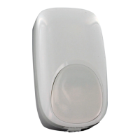
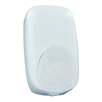
For improved anti-mask
performance the look-down
mirror is disabled. To enable
look-down remove the mask.
Corner
Mount Hole*
*Note: If the Rear
Tamper function is not
required, do not use the
mounting holes in the
Rear Tamper Breakaway
Tab.
Fault, Alarm and Tamper configured to two loops.
Fault, Alarm and Tamper configured to one loop.
FAULT
(RF)
TAMPER
(RT)
ALARM
(RA)
E
F
A
B
C
D
A
B
C
D
Factory default
settings are
shown in grey.
2.2K
3K
1K
2.2K
4.7K
5.6K
1K
2.2K
4.7K
5.6K
Jumper
Position EOL Value
• Connect wires as shown using 0.2 - 1.3 mm
2
wire size.
Observe proper polarity.
• If not using the integrated EOL resistors, remove jumpers from
all pins.
• If using the integrated EOL resistors:
1. Connect the sensor to the panel (see wiring diagrams on
the right; if using the two loop option, also cut link W1).
2. Place the jumpers on the appropriate fault, tamper and
alarm pin options (see table below).
Notes:
• Consult the Control Panel manual to determine proper EOL
selection.
• Fit only one jumper each for the fault, tamper and alarm
EOL settings.
Rear Tamper Breakaway
Tab: Best if mounted to a
stud, solid wood, or with
a robust wall anchor.